A Cisco Unified Border Element can be implemented in VoIP networks to enhance VoIP network interoperability. This section describes how to implement Cisco UBE routers to support protocol interworking between H.323 and SIP networks.
Protocol Interworking Command
To enable protocol interworking, use the allow-connections from-type to to-type command in voice service configuration mode. The from-type and to-type options specify the signaling protocols, as detailed in Table 9-2.
Table 9-2 allow-connections Syntax Description
|
Parameter |
Description |
|
from-type |
Originating endpoint type. The following choices are valid: h323—H.323 |
|
sip—SIP |
|
|
To |
Indicates that the argument that follows is the connection target. |
|
to-type |
Terminating endpoint type. The following choices are valid: |
|
h323—H.323 |
|
|
sip—SIP |
When interworking H.323 and SIP, the configuration is unidirectional; thus, if bidirectional interworking is required, you need to configure the mirroring statement as well. For example, if bidirectional H.323 to SIP interworking is required, you need to configure allow connections h323 to sip as well as allow connections sip to h323.
Figure 9-14 and Example 9-1 illustrate a sample protocol interworking configuration.
Figure 9-14 Protocol Interworking Topology Example
Example 9-1 Protocol Interworking Configuration
Configuring H.323-to-H.323 Interworking
H.323-to-H.323 gateway configuration provides a network-to-network demarcation point between independent VoIP and video networks for billing, security, call-admission control, QoS, and signaling interworking. It performs most of the functions of a PSTN-to-IP gateway but joins two H.323 VoIP call legs.
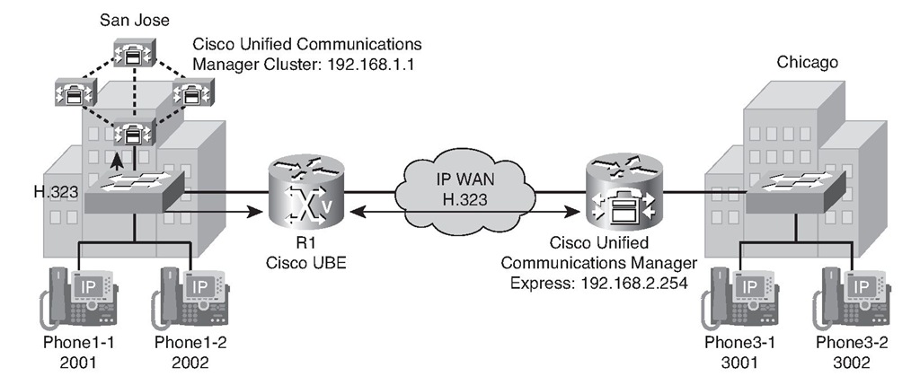
Figure 9-15 shows a sample scenario used to configure H.323-to-H.323 interworking for a Cisco UBE router. The Cisco Unified Communications Manager cluster in San Jose is connected with the Cisco Unified Communications Manager Express router in Chicago using a Cisco UBE router.
To configure H.323-to-H.323 interworking between a Cisco Unified Communications Manager cluster and a Cisco Unified Communications Manager Express gateway, follow these steps:
Step 1. Enable H.323-to-H.323 interworking.
Step 2. Configure the H.323 dial peers on the Cisco UBE router to allow call routing between the Cisco Unified Communications Manager cluster and Cisco Unified Communications Manager Express router.
Figure 9-15 H.323-to-H.323 Interworking Scenario
Step 1: Enabling H.323-to-H.323 Interworking
By default, a Cisco IOS gateway will not allow connections between two VoIP dial peers. To change this behavior and allow H.323-to-H.323 connections, use the allow-connections h323 to h323 command in voice service configuration mode, as shown in Example 9-2.
Example 9-2 Enabling H.323 Protocol Interworking
Step 2: Configuring H.323 Dial Peers
After H323-to-H323 calls have been allowed, configure the appropriate dial peers to route between the Cisco Unified Communications Manager cluster and the Cisco Unified Communications Manager Express router. No special configuration on the dial peers is required. Example 9-3 illustrates this dial-peer configuration.
Example 9-3 H.323 Dial Peers
Configuring H.323-to-SIP Interworking
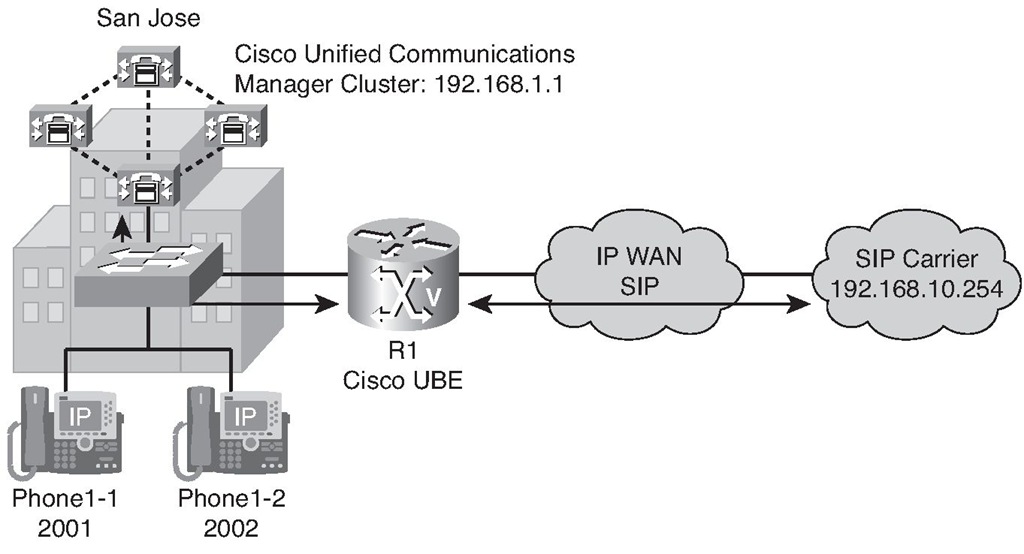
Figure 9-16 shows a sample scenario used to configure H.323-to-SIP interworking with a Cisco UBE router. The Cisco Unified Communications Manager cluster in San Jose routes calls to the SIP carrier via a Cisco UBE router. The connection between the Cisco Unified Communications Manager and the Cisco UBE router is H.323 and the connection between the Cisco UBE router and the SIP carrier is SIP.
Figure 9-16 H.323-to-SIP Interworking Scenario
You can follow these steps to configure H.323-to-SIP interworking: Step 1. Enable H.323-to-SIP interworking.
Step 2. Configure H.323 and SIP dial peers to route international calls between the Cisco Unified Communications Manager cluster and the SIP carrier.
Step 1: Enabling H.323-to-SIP Interworking
As with an H.323-to-H.323 connection, by default a Cisco IOS gateway will not allow connections between an H.323 and a SIP VoIP dial peer. To change this behavior and allow H.323-to-SIP connections, use the allow-connections h323 to sip command in voice service configuration mode. Then issue the allow-connections sip to h323 command to enable SIP to H.323 calls, as demonstrated in Example 9-4.
Example 9-4 H.323-to-SIP Interworking
Step 2: Configuring Dial Peers
For a SIP (rtp-nte)-to-H.323 (h245-alphanumeric) call via a Cisco UBE router, if any RTP named telephony event (NTE) packets are sent before the H.323 endpoint answers the call, the DTMF signal is not heard on a terminating gateway (TGW).
Note debug output reveals that the H245 out-of-band messages are sent to the TGW. However, the digits are not heard on the phone.
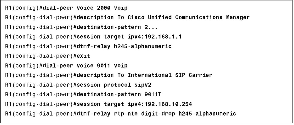
To avoid sending both in-band and out-of-band tones to the outgoing leg when sending Cisco UBE calls in-band (rtp-nte) to out-of-band (h245-alphanumeric), configure the dtmf-relay rtp-nte digit-drop command on the incoming SIP dial peer. On the H.323 side, configure either dtmf-relay h245-alphanumeric or dtmf-relay h245-signal. This can also be used for H.323-to-SIP calls. Example 9-5 illustrates this dial-peer configuration.
Example 9-5 Dial-Peer Configuration


