Introduction
In the latest release of FireWall-1 NG, Feature Pack 3 (NG-FP3), Check Point Software has introduced many new features.This topic discusses some fundamental changes in software’s methods of operation from 4.x to NG.Some of the key changes in NG include a much faster kernel, a revamp of static Network Address Translation (NAT), and the introduction of automatic Address Resolution Protocol (ARP), to name just a few. We will highlight the new features of the NG product and how these changes affect your FireWall-1 environment. For readers who are new to FireWall-1, this section outlines the ways that some of these key features function and what they can provide for your deployment.
NG is not an upgrade from 4.x. Check Point has spent a number of years redesigning the FireWall-1 product; NG represents that redesign. Some of the functions that were available in the 4.x version have been removed, replaced, or simply restructured from the ground up. NG contains new features that existing administrators will need to review before implementing.
The first area in which the NG product has significantly improved is in its throughput. NG increases the throughput on all platforms. (Visit www.checkpoint.com/ products/choice/platforms/platforms_matrix.html for the specifics on platform and performance numbers.) For example, the Windows platform with Dual Xeon processors, 1GB RAM, and two 64-bit PCI Gigabit Ethernet cards will provide approximately 625Mbps throughput, with a platform price of around $5,000.This is a substantial improvement over the 4.x platform. Check Point also has added SecurePlatform, which provides a secure operating system to use with the Check Point software. If the hardware is used with SecurePlatform, NG can provide greater than 3+Gbps for the same $5,000 hardware cost!
Static NAT has also changed. With the ability to perform NAT on the client side of the connection, Automatic ARP functions, NG can make your Static NAT creations on hosts very quick and simple operations. In some areas, the NAT changes could change the way your network needs to be configured, so be sure to review this section well if you plan to utilize client-side NAT.
Lastly, in some environments, upgrading your product might not be the best solution. Rebuilding your firewall might be a better solution. We dig into these scenarios and provide insight into how best to get your 4.x firewall up to NG. Now let’s review these changes.
You have installed your firewall and are now configuring the Rule Base, objects, and sys-temwide parameters. Although the process of configuring the rules is relatively straight forward, the NAT configuration always seems to increase the frustration level for firewall administrators.The security policy is a top-to-bottom list of matching criteria for packets that reach the firewall. With a rule in place to accept the desired traffic, the "What happens next?" question complicates matters when you’re implementing NAT. We have two basic methods of applying address translation: Static and Hide. In Hide mode, you are using one IP address to serve as the source IP for multiple clients—a many-to-one sub-stitution.The common application of Hide mode is to provide clients with a legal IP address to be able to access resources on the Internet. Check Point’s Hide mode NAT is synonymous with Port Address Translation (PAT). Static NAT replaces the physical IP address of a single device with a different IP address, a one-to-one substitution. Typically, this method is used for making resources available from the Internet.
NAT does not require us to use valid Internet addresses as the translated address. Although this is the most common application, there are no restrictions on using non-routable IP addresses for the translation. For the examples that follow, the translated addresses are routable.
Both Hide and Static NAT can take place on either interface of your firewall with NG-FP3.This does not imply that you only have two interfaces on your firewall; typically, there are three or more. For an individual packet traversing a firewall, there are only two interfaces. The first interface is where the packet arrives at the firewall and makes a comparison to either the Rule Base or the firewall state table in the inbound direction. The second interface is where the firewall forwards the packet after being accepted in the outbound direction. The origin of the packet is the determinant for referring to an interface to as either inbound or outbound. Version 4.x did not provide the flexibility to modify where the translation occurred; it was always on the outbound interface. Pre-NG-FP3 manual NAT rules applied only to the outbound direction. NG-FP3 has an option for translating manual rules on the inbound interface.
Tools & Traps…
Address Translation Rules: Automatic vs. Manual
There are two options for creating address translation rules: automatic and manual. Automatic rules are created from an object by selecting the check box for Add Automatic Address Translation Rules in the NAT configuration options of that particular object. These rules may not be modified or deleted from the SmartDashboard Address Translation rules screen. The comment will say Automatic Rule (see the network object data). Automatic rules will always be contiguous, and Static NAT rules will appear above Hide NAT rules. As long as an object has automatic NAT enabled, these rules will exist in any security policy created.
Manual rules are created by inserting rules in the SmartDashboard Address Translation rules screen. Manual rules can only be inserted before or after the automatic rules. You must create an object for the node or network and an object that represents the NAT address. This increases the number of objects that need to be created and managed. Pre-NG-FP3 manual Static NAT rules did the destination address translation only on the server side. NG-FP3 has an option for enabling destination translation on the client side. Both types may be used in the same security policy; however, manual NAT rules will not carry over when you create a new policy.
Reasons for creating manual NAT rules are influenced by your production requirements. One common scenario is using a manual NAT rule to not do address translation between networks. This situation could occur where a virtual private network (VPN) is configured and the encryption domain is defined using the internal addresses or where there is a wide area network (WAN) connection. Add a manual rule, configure the source and destination section for the original packet, and leave the settings as original in the translated packet. This rule must come before the automatic rules.
Another scenario for using manual NAT rules is one in which you want to translate the destination address based on the service type. You have a limited number of legal IP addresses and need to have different server types using the same IP. It is important to remember the change in FP3 allowing for destination translation on the client side when you upgrade from earlier NG versions.
You must account for certain considerations within your infrastructure when you’re selecting either mode. The changes are not intended to make your life more difficult as a firewall administrator or to provide job security.These features are intended to allow the flexibility necessary for the complexity of our network topologies. Static NAT in 4.x is very rigid, with specific configuration steps. NG is designed to provide dynamic and automatic configuration parameters to support simple and complex network designs.
Server-Side NAT
Server-side NAT is the default when you’re using static NAT in version 4.x. Say that we have a server that we want to make available using a different IP address from the one physically assigned. The reasons for doing this are either to provide a legal address where there is currently an illegal address or to mask the physical address. The translation of the destination address takes place on the interface on the server side of the firewall, the outbound interface.
Let’s look at the flow of a packet through this process and the configuration steps necessary to make this work. We have a Web server www.newyork.com with a physical address of 10.1.1.3 that we want to make available to the Internet with a 38.1.1.3 address. Once the valid IP address is selected and added to the Domain Name Server (DNS) record, we need to configure the firewall so that the communication functions properly.
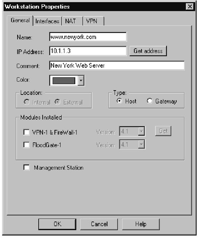
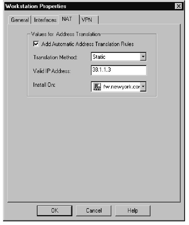
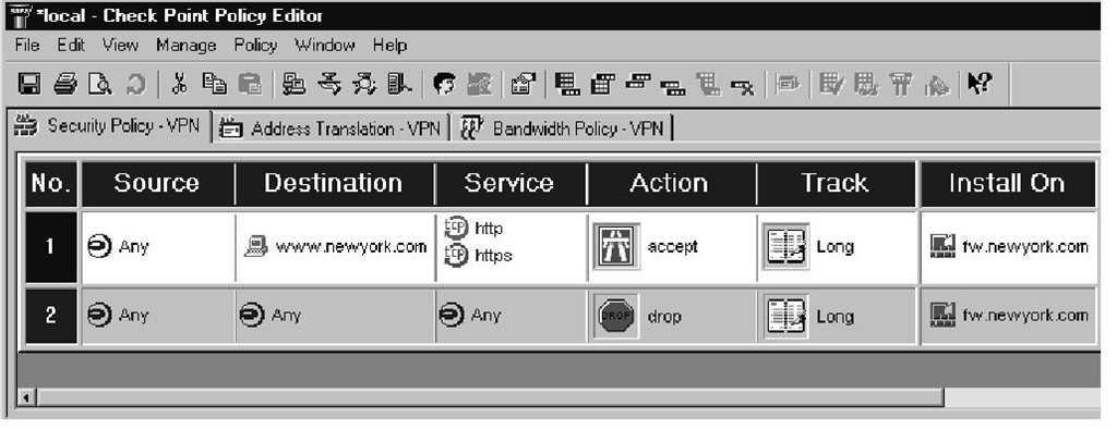
The first step in either version is to create the workstation object using the physical, nonroutable IP address, as shown in Figure 1.1.The second step is to define the NAT configuration settings for this object using a legal IP address with Static NAT, as illustrated in Figure 1.2. Checking the box for Add Automatic Address Translation Rules will generate the inbound and outbound rules.The third step is to configure a rule that accepts traffic destined for this server—in our case, http or https, as shown in Figure 1.3.
Figure 1.1 Web Server Object
Figure 1.2 Web Server NAT
Figure 1.3 Firewall Rule
If you are using NG with default settings with a functional Automatic ARP environment, you are done with the process.The 4.x environment has a few additional steps. For seasoned veterans, the next couple of sections are merely a review.
Version 4.x Destination Static NAT
This section follows the configuration steps relative to the packet flow. No Automatic ARP is available when 4.x is used; we need to define a means to let the border router know where to send the packet—the firewall’s external network interface card (NIC). Accomplishing this goal requires creation of an ARP entry with the legal NAT IP address and the MAC address of the external NIC on the firewall. Another method is to add a static host route on the border router that routes the legal NAT IP to the firewall’s external interface.
Now that the packet has arrived at the firewall, we need to make sure that the firewall knows where to forward the packet. No translation has taken place, so the network layer on the firewall will want to send the packet back out the external interface. The destination address is still the legal IP that is part of the network between the border router and the firewall. Create a static host route on the firewall routing the legal IP address to the internal host address. This forwards the packet out the internal interface.
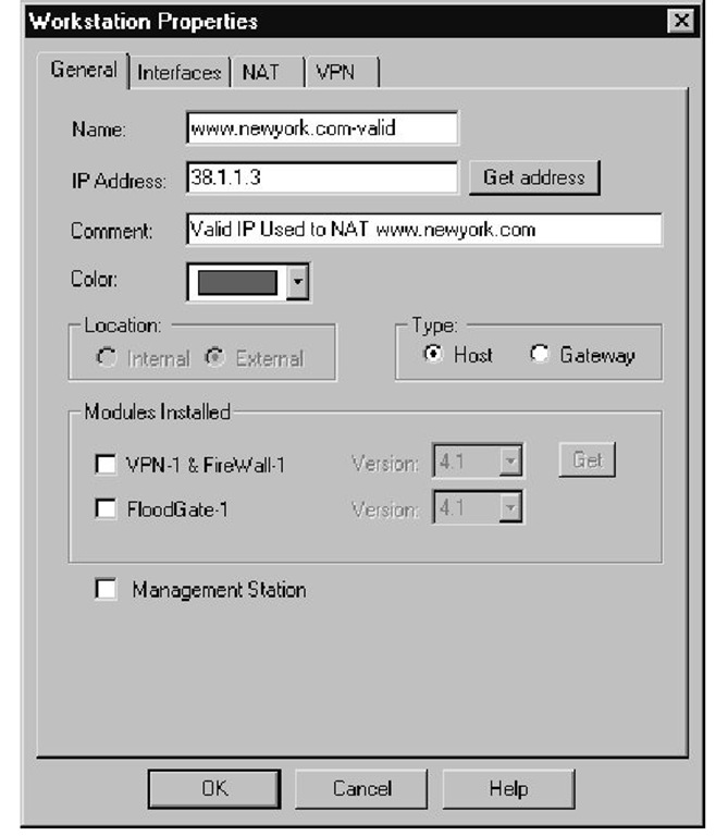
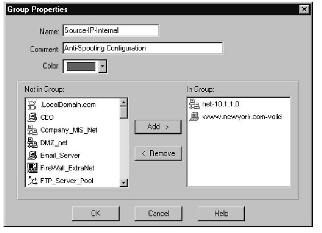
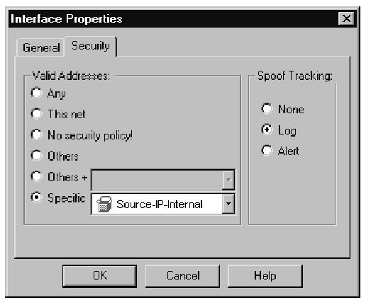
Finally, at the internal interface on the server side of the firewall, the destination address is changed from the legal to the nonroutable IP address. The server then receives the packet. The server then sends a reply packet, the source address being the nonroutable IP, to the default gateway. The firewall then changes the source IP back to the legal address at the internal interface.The packet is dropped here based on Rule 0 unless the antispoofing is modified to accept packets with a source IP from the network address range and the legal IP. Properly configuring the antispoofing requires you need to complete the following steps. First you must create a network object to represent the IP network physically connected to the internal interface of the firewall (see Figure 1.4). Next you must create a workstation object representing the NAT (legal) IP address being used for the Web server, as shown in Figure 1.5. Add both of these objects to a group, and use this group for the antispoofing settings on the internal interface (see Figure 1.6). Finally, you need to select the Specific option on the Security tab for the internal interface, then use this object you just created, as shown in Figure 1.7. It is very important to set the Spoof Tracking settings to Log. The default setting is no tracking; choosing the default would make troubleshooting this problem a little difficult. The reply packet is then routed back to the client.
Figure 1.4 Network Object
Figure 1.5 Workstation Object for NAT(Legal) IP
Figure 1.6 Group Object
Figure 1.7 Antispoofing
