End-to-end QoS means that all the network components between the end points of a network communication dialogue need to implement appropriate QoS mechanisms consistently. If, for example, an enterprise (customer) uses the services and facilities of a service provider for connectivity between its headquarters and branch offices, both the enterprise and the service provider must implement the proper IP QoS mechanisms. This ensures end-to-end QoS for the packets going from one enterprise location to the other, traversing through the core network of the service provider.
At each customer location where traffic originates, traffic classification and marking need to be performed. The connection between the customer premises equipment and the provider equipment must have proper QoS mechanisms in place, respecting the packet markings. The service provider might trust customer marking, re-mark customer traffic, or encapsulate/tag customer traffic with other markings such as the EXP bits on the MPLS label. In any case, over the provider core, the QoS levels promised in the SLA must be delivered. SLA is defined and described in the next section. In general, customer traffic must arrive at the destination site with the same markings that were set at the site of origin. The QoS mechanisms at the customer destination site, all the way to the destination device, complete the requirements for end-to-end QoS.
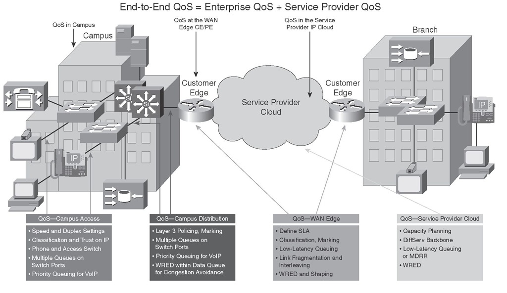
Figure 6-3 shows several key locations within customer and provider premises where various QoS mechanisms must be deployed. As the figure points out, end-to-end QoS is accomplished by deploying proper QoS mechanisms and policies on both the customer (enterprise) devices and the service provider (core) devices.
Figure 6-3 End-to-End QoS: Features and Related Implementation Points
Correct end-to-end per-hop behavior (PHB) for each traffic class requires proper implementation of QoS mechanisms in both the enterprise and the service provider networks. In the past, IP QoS was not given much attention in enterprise campus networks because of abundant available bandwidth. Today, however, with the emergence of applications such as IP Telephony, videoconferencing, e-learning, and mission-critical data applications in the customer campus networks, many factors such as packet drop management, buffer management, queue management, and so on, in addition to bandwidth management, are required within the campus to minimize loss, delay, and jitter.
Figure 6-3 displays some of the main requirements within the campus and provider building blocks constituting the end-to-end QoS. Proper hardware, software, and configurations such as buffer settings and queuing are the focus of the access layer QoS. Policing, marking, and congestion avoidance are implemented at the campus distribution layer. At the WAN edge, it is often required to make some complex QoS configurations related to the subscribed WAN service. Finally, in the service provider IP core, congestion-management and congestion-avoidance are the main mechanisms in operation; the key QoS mechanisms used within the service provider core IP network are low-latency queuing (LLQ) and weighted random early detection (WRED).
QoS Service Level Agreements (SLAs)
An SLA is a contractual agreement between an enterprise (customer) and a service provider regarding data, voice, and other service or a group of services. Internet access, leased line, Frame Relay, and ATM are examples of such services. After the SLA is negotiated, it is important that it is monitored for compliance of the parties involved with the terms of the agreement. The service provider must deliver services as per the qualities assured in the SLA, and the customer must submit traffic at the rates agreed upon, to receive the QoS level assured by the SLA. Some of the QoS parameters that are often explicitly negotiated and measured are delay, jitter, packet loss, throughput, and service availability. The vast popularity of IP Telephony, IP conferencing, e-learning, and other real-time applications has made QoS and SLA negotiation and compliance more important than ever.
Traditionally, enterprises obtained Layer 2 service from service providers. Virtual circuits (VC), such as permanent VCs, switched VCs, and soft PVCs, provided connectivity between remote customer sites, offering a variety of possible topologies such as hub and spoke, partial mesh, and full mesh. Point-to-point VCs have been the most popular type of circuits with point-to-point SLA assurances from the service provider. With Layer 2 services, the provider does not offer IP QoS guarantees; the SLA is focused on Layer 1 and Layer 2 measured parameters such as availability, committed information rate (CIR), committed burst (Bc), excess burst (Be), and peak information rate. WAN links sometimes become congested; therefore, to provide the required IP QoS for voice, video, and data applications, the enterprise (customer) must configure its equipment (WAN routers) with proper QoS mechanisms. Examples of such configurations include Frame Relay traffic shaping, Frame Relay fragmentation and interleaving, TCP/RTP header compression, LLQ, and class-based policing.
In recent years, especially due to the invention of technologies such as IPsec VPN and MPLS VPN, most providers have been offering Layer 3 services instead of, or at least in addition to, the traditional Layer 2 services (circuits). In summary, the advantages of Layer 3 services are scalability, ease of provisioning, and service flexibility. Unlike Layer 2 services where each circuit has a single QoS specification and assurance, Layer 3 services offer a variety of QoS service levels on a common circuit/connection based on type or class of data (marking). For example, the provider and the enterprise customer might have an SLA based on three traffic classes called controlled latency, controlled load, and best effort. For each class (except best effort) the SLA states that if it is submitted at or below a certain rate, the amount of data drop/loss, delay, and jitter will be within a certain limit; if the traffic exceeds the rate, it will be either dropped or re-marked (lower).
It is important that the SLA offered by the service provider is understood. Typical service provider IP QoS SLAs include three to five traffic classes: one class for real-time, one class for mission-critical, one or two data traffic classes, and a best-effort traffic class. The real-time traffic is treated as a high-priority class with a minimum, but policed, bandwidth guarantee. Other data classes are also provided a minimum bandwidth guarantee. The bandwidth guarantee is typically specified as a percentage of the link bandwidth (at the local loop). Other parameters specified by the SLA for each traffic class are average delay, jitter, and packet loss. If the interface on the PE device serves a single customer only, it is usually a high-speed interface, but a subrate configuration offers the customer only the bandwidth (peak rate) that is subscribed to. If the interface on a PE device serves multiple customers, multiple VLANs or VCs are configured, each serving a different customer. In that case, the VC or subinterface that is dedicated to each customer is provisioned with the subrate configuration based on the SLA.
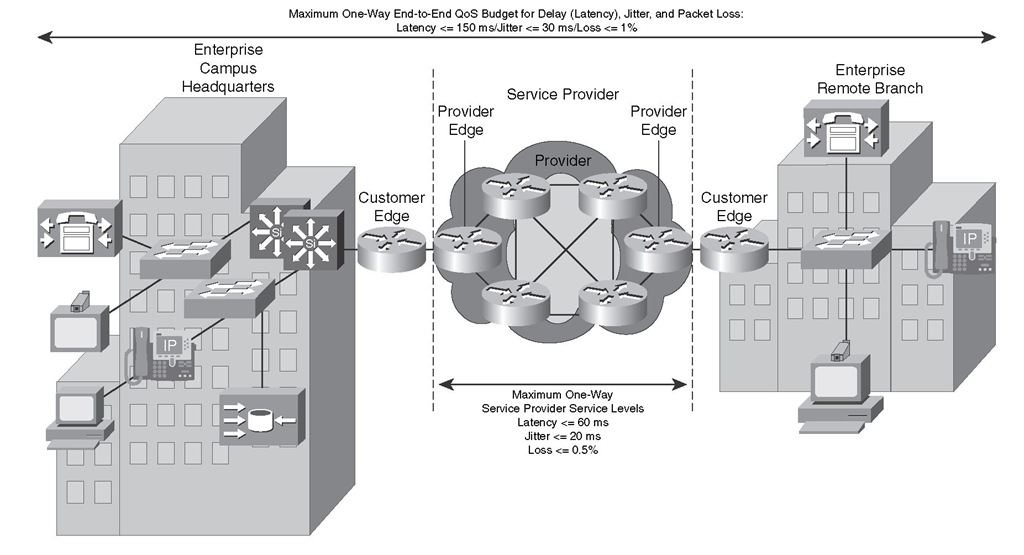
Figure 6-4 displays a service provider core network in the middle offering Layer 3 services with IP QoS SLA to its customer with an enterprise campus headquarters and an enterprise remote branch. The customer in this example runs IP Telephony applications such as VoIP calls between those sites.
To meet the QoS requirements of the typical telephony (VoIP) applications, the enterprise must not only negotiate an adequate SLA with the provider, but it also must make proper QoS configurations on its own premise devices so that the end-to-end QoS becomes appropriate for the applications. In the example depicted in Figure 6-4, the SLA guaranteed a delay (latency) <= 60 ms, jitter <= 20 ms, and packet loss <= 0.5 percent. Because the typical end-to-end objectives for delay, jitter, and packet loss for VoIP are <= 150 ms, <= 30 ms, and <= 1 percent, respectively, the enterprise must make sure that the delay, jitter, and loss within its premises will not exceed 90 ms, 10 ms, and 0.5 percent, respectively.
Figure 6-4 Example for IP QoS SLA for VoIP
Enterprise Campus QoS Implementations
Provisioning QoS functions and features within campus networks on access, distribution, and core switches is a part of end-to-end QoS. This is in large part due to the growth of IP Telephony, video conferencing, e-learning, and mission-critical applications within enterprise networks. Certain efforts are spent on access devices, whereas others are spent on distribution and core equipment to minimize packet loss, delay, and jitter. Figure 6-5 shows the series of devices—all the way from end-user workstation (PC) to the core campus LAN switch and WAN edge router—that exist in a typical campus LAN environment.
Figure 6-5 Typical Campus LAN Devices
Important guidelines for implementing QoS in campus networks are as follows:
■ Classify and mark traffic as close to the source as possible—Classifying and marking packets as close to the source as possible, and not necessarily by the source, eliminates the need for classification and marking efforts to be repeated and duplicated at various network locations. However, marking of all end devices cannot be trusted either, because it opens the door to abuse.
■ Police traffic as close to the source as possible—Policing unwanted traffic as close to the source as possible is the most efficient way of handling excessive and possibly invasive and malicious traffic. Unwanted traffic, such as denial of service (DoS) attacks and worm attacks, can cause network outage by overwhelming network resources, device CPUs, and memories.
■ Establish proper trust boundaries—Trust Cisco IP phones marking, but not the markings of user workstations (PCs).
■ Classify and mark real-time voice and video as high-priority traffic— Higher priority marking for voice and video traffic gives them queue assignment, delay, jitter, and drop advantage over other types of traffic.
■ Use multiple queues on transmit interfaces—This minimizes transmit queue congestion and packet drops and delays due to transmit buffer congestion.
■ When possible, perform hardware-based rather than software-based QoS—Contrary to Cisco IOS routers, Cisco Catalyst switches perform QoS functions in special hardware (application-specific integrated circuits, or ASICs). Use of ASICs rather than software-based QoS is not taxing on the main processor and allows complex QoS functions to be performed at high speeds.
Congestion is a rare event within campus networks; if it happens, it is usually instantaneous and does not sustain. However, critical and real-time applications (such as Telephony) still need the protection and service guarantees for those rare moments. QoS features such as policing, queuing, and congestion avoidance (WRED) must be enabled on all campus network devices where possible. Within campus networks, link aggregation, oversubscription on uplinks, and speed mismatches are common causes of congestion. Enabling QoS within the campus is even more critical under abnormal network conditions such as during DoS and worm attacks. During such attacks, network traffic increases and links become overutilized. Enabling QoS features within the campus network not only provides service-level guarantees for specific application types, but it also provides network availability assurance, especially during network attacks.
In campus networks, access switches require these QoS policies:
■ Appropriate trust, classification, and marking policies
■ Policing and markdown policies
■ Queuing policies
The distribution switches, on the other hand, need the following:
■ DSCP trust policies
■ Queuing policies
■ Optional per-user micro-flow policies (if supported)
WAN Edge QoS Implementations
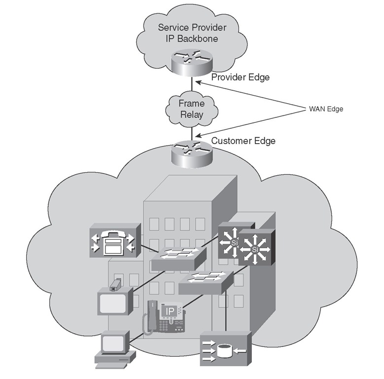
WAN edge QoS configurations are performed on CE and PE devices that terminate WAN circuits. Commonly used WAN technologies are Frame Relay and ATM. Important QoS features implemented on the CE and PE devices are LLQ, compression, fragmentation and interleaving, policing, and shaping. Figure 6-6 shows a customer site connected to a provider IP network through a Frame Relay connection between a CE device and a PE device. Note that a similar connection between the CE and the PE devices exists at the remote site.
Figure 6-6 WAN Edge QoS Implementation Points
For the traffic that is leaving a local customer site through a CE device going toward the provider network and entering it through a PE device, output QoS mechanisms on the CE device and input QoS mechanisms on the PE device must be implemented. The implementation will vary somewhat, depending on whether the CE device is provider managed—in other words, if it is under the control of the provider. Table 6-2 shows the QoS requirements on the CE and the PE devices in both cases: when the CE device is provider managed, and when the CE device is not provider managed. When the CE device is provider managed, the service provider manages and performs the QoS policies and configurations. Otherwise, the customer enterprise controls the QoS policies and configures the CE device.
Table 6-2 QoS Mechanisms Necessary for Traffic Leaving a Customer Site
|
Managed CE |
Unmanaged CE |
|
The service provider controls the output QoS policy on the CE. |
The service provider does not control the output QoS policy on the CE. |
|
The service provider enforces SLA using the output QoS policy on the CE. |
The service provider enforces SLA using the input QoS policy on the PE. |
|
The output policy uses queuing, dropping, and shaping. |
The input policy uses policing and marking. |
|
Elaborate traffic classification or mapping of existing markings takes place on the CE. |
Elaborate traffic classification or mapping of existing markings takes place on the PE. |
|
LFI* and compressed RTP might be necessary. * LFI = link fragmentation and interleaving |
When the CE device is provider managed, the provider can enforce the SLA by applying an outbound QoS service policy on the CE device. For example, an LLQ or class-based weighted fair queueing (CBWFQ) can be applied to the egress interface of the CE device to provide a policed bandwidth guarantee to voice and video applications and a minimum bandwidth guarantee to mission-critical applications. You can use class-based shaping to rate-limit data applications. You can apply congestion avoidance (WRED), shaping, compression (cRTP), and LFI outbound on the managed CE device. When the CE device is not provider managed, the provider enforces the SLA on the ingress interface of the PE device using tools such as class-based policing. Policed traffic can be dropped, re-marked, or mapped (for example, DSCP to MPLS EXP).
At the remote site, where the traffic leaves the provider network through the PE router and enters the enterprise customer network through the CE device, most of the QoS configurations are configured on the PE device (outbound), regardless of whether the CE device is managed. The service provider enforces the SLA using output QoS policy on the PE device. Output policy performs congestion management (queuing), dropping, and possibly shaping. Other QoS techniques such as LFI or cRTP can also be performed in the PE device. CE input policy is usually not necessary; of course, the configuration of the CE device that is not provider managed is at the discretion of the enterprise customer.


