WCS Configuration Examples
The WCS configuration first requires an authorized login. Several configuration steps must take place after the initial authorized login, such as adding devices and site maps.
WCS Login Steps
The Cisco WCS Server login involves three major steps:
Step 1 Start Microsoft Internet Explorer version 6.0 or later.
Step 2 Enter https://localhost in the address bar when the Cisco WCS user interface is on a Cisco WCS server. Enter https://wcs-ip-address when the Cisco WCS interface is on any other workstation.
Step 3 Enter your username and password on the login page. The default username is root, and the default password is public.
NOTE Some Cisco WCS features might not function properly if you use a web browser other than Internet Explorer 6.0 or later.
Changing the Root Password
The following are the steps to change the root password:
Step 1 Log in as root.
Step 2 Select Administration > Accounts.
Step 3 From the User Name column, click root.
Step 4 Enter a new password in the New Password text box, and retype the new password in the Confirm New Password text box.
Step 5 Click Submit.
Adding a Wireless LAN Controller
The first step when adding a WLC is gathering the IP address of the controller service port. Use the following steps to add the controller:
Step 1 Log into Cisco WCS.
Step 2 Choose Configure > Controllers from the All Controllers page.
Step 3 Click the Select a Command drop-down menu, choose Add Controller, and click GO.
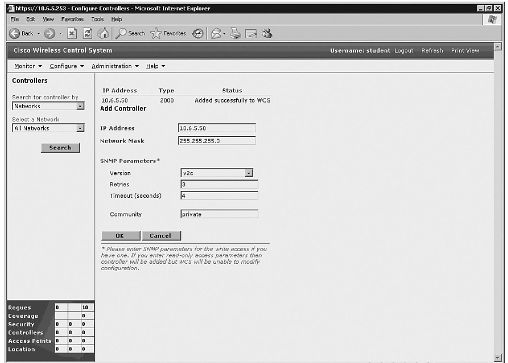
Step 4 Enter the controller IP address, network mask, and required SNMP settings in the Add Controller fields (see Figure 10-4).
Figure 10-4 Adding a WLC
Step 5 Click OK.
NOTE Cisco WCS displays the Please Wait dialog box during the initial contact and while it is being added to the Cisco WCS database. Control is returned to the Add Controller page again upon success.
Controller management through the dedicated service port of the controller improves security. Some controllers do not have dedicated service ports, such as the Cisco 2000 Series WLC, which must use the controller management interface. Moreover, if a controller service port is disabled, the management interface of the controller must be used.
An issue might arise in which the WCS cannot communicate with the controller. A Discovery Status dialog box appears with a message "No response from device, check SNMP." A few checks can verify the correct settings:
■ A bad IP address on the controller service port
■ A blocked network path can be verified by pinging the controller from the WCS server
■ SNMP mismatch between the controller and Cisco WCS
You can continue to add or return additional controllers to the All Controllers page by choosing Configure > All Controllers.
Configuring Access Points
To view a summary of all Cisco LWAPs in the Cisco WCS database, choose Configure > Access Points. This page allows you to add third-party APs and remove selected Cisco LWAPs. When a WLC is added to WCS, it automatically adds all the LWAPs, too.
NOTE There is no need to add Cisco LWAPs to the Cisco WCS database. The operating system software automatically adds Cisco LWAPs as they associate with existing Cisco WLCs in the Cisco WCS database.
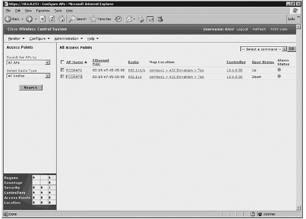
The All Access Points page displays the AP name, radio type, map location, controller, port, operational status, and alarm status. Figure 10-5 shows the All Access Points page.
Figure 10-5 All Access Points Page
WCS Map
Cisco WCS can use real floor, building, and campus plans to view the physical and RF environments together. This section discusses adding a campus map and a new building.
Adding a Campus Map
Use the following steps to add a campus map:
Step 1 Save the map in a format such as .png, .jpg, .jpeg, or .gif. Do not worry about the size, because WCS will manage it.
Step 2 Browse to the map and import it from anywhere in the file system.
Step 3 Choose the Monitor tab.
Step 4 Choose Maps.
Step 5 From the Select a Command drop-down menu, choose New Campus and click Go.
Step 6 On the New Campus page, enter the campus name and contact.
Step 7 Choose Browse, and select the campus graphic name.
Step 8 Choose Maintain Aspect Ratio so that WCS does not distort the map. Step 9 Enter the horizontal and vertical span size in feet.
NOTE The campus horizontal and vertical spans should be larger than any building or floor plan to be added to the campus.
Step 10 Click OK.
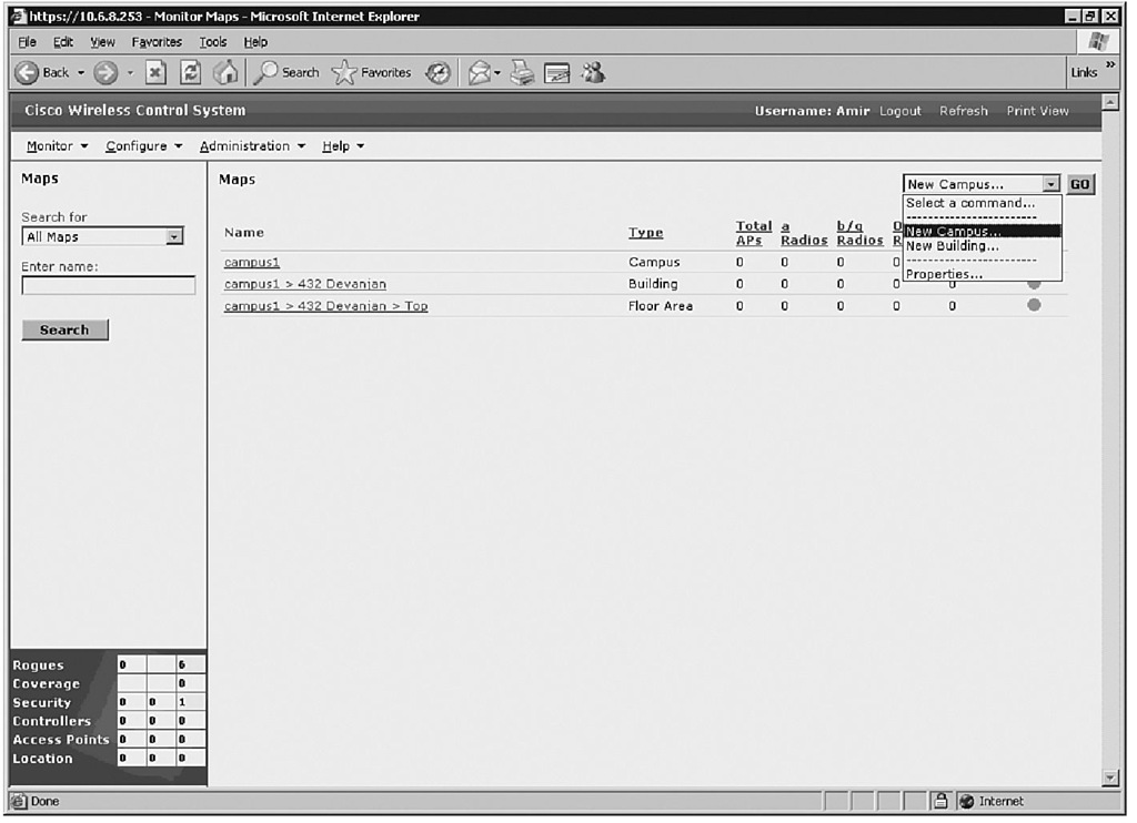
Cisco WCS displays the Maps page, which lists maps in the database along with map types and their status. Figure 10-6 shows a sample Maps page.
Figure 10-6 Maps Page
A WCS map can start out as either a building or a campus map. The building map can be a single entity or part of the campus map. Moreover, the campus map can have an outdoor coverage area.
Adding a New Building
Buildings can be added without maps. Use the following steps to add a building:
Step 1 Choose the Monitor tab.
Step 2 Choose Maps.
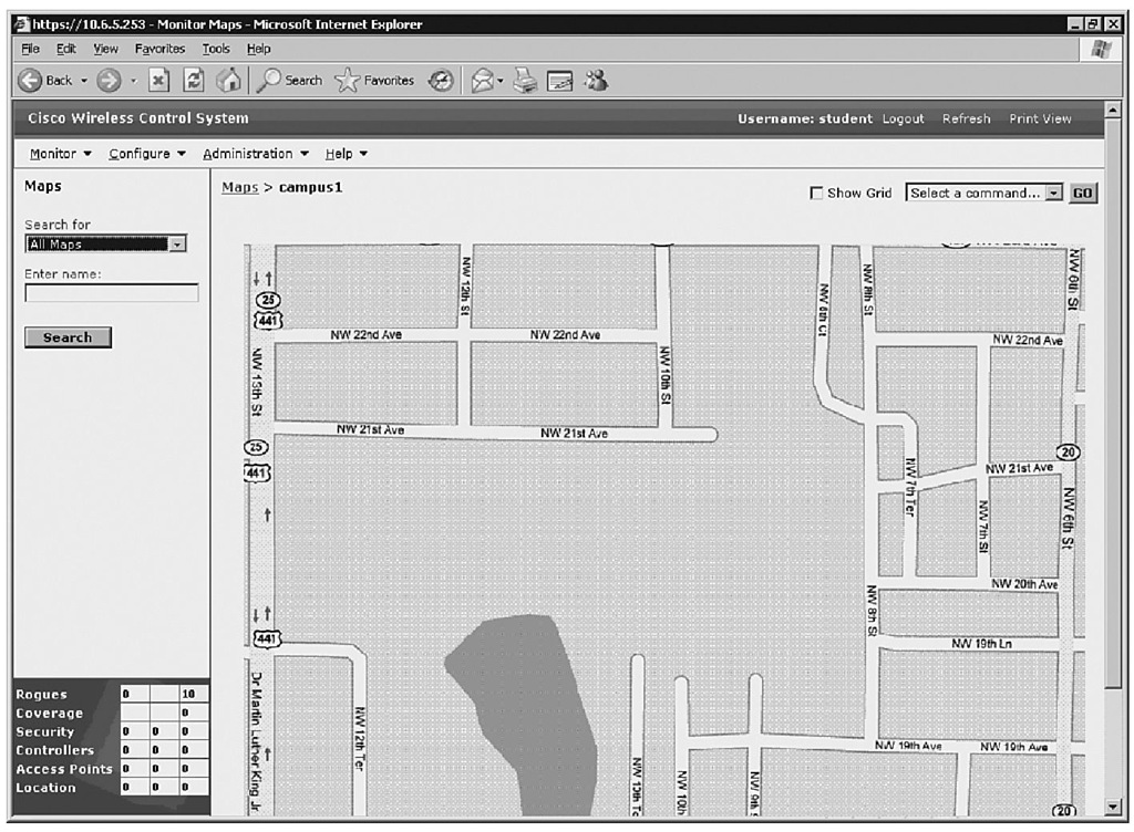
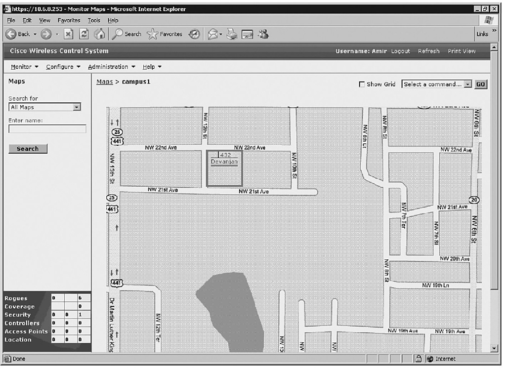
Step 3 When you choose the desired campus, WCS displays the Campus page (see Figure 10-7).
Figure 10-7 Campus Page
Step 4 From the Select a Command drop-down menu, choose New Building and click Go.
Step 5 Create a virtual building to organize related floor plan maps by entering the building name, contact, number of floors and basements, and the horizontal and vertical span size in feet.
NOTE Ctrl-Left-Select is an alternative key stroke combination to resize the bounding area in the upper left corner of the campus map. When changing the bounding size, the building horizontal span and vertical span parameters automatically adjust to match your changes.
Step 6 Choose Place to put the scaled rectangular building on the campus map. Figure 10-8 shows the placement of a new building.
Figure 10-8 Adding a New Building
Step 7 Move the building to the desired location. Step 8 Choose Save.
NOTE A hyperlink that is associated with the building links the corresponding Maps page.
Rogue Access Point Detection
The process flow of a rogue AP being detected in a WLAN environment is based on the LWAPs already being powered up and associated to their controllers. The WLC detects a rogue AP and immediately notifies WCS, which creates a rogue AP alarm that appears in the lower-left corner of the user interface pages. Simply selecting the indicator displays the Rogue AP Alarms page.
Rogue Access Point Alarms
The alarms for rogue APs are naturally listed on the Rogue Access Point Alarms page. This page details the severity, the rogue MAC address, the vendor, the radio type, the strongest AP RSSI, the date and time, the channel number, and the SSID. You can view further details by clicking the link in the Rogue MAC Address column. Then you see the associated Alarms > Rogue AP MAC Address page. To view rogue AP information using the menu bar, choose Monitor > Alarms > Rogue AP Alarms.
You can handle the alarms by checking a box to the left of the severity and manage them using the Select a Command drop-down menu. The choices available are Assign to Me, Unassign, Delete, Clear, or Email Notification.
Rogue Access Point Location
To see the rogue AP calculated location on a map, choose Map from the Rogue AP MAC Address page, or from the menu bar choose Monitor > Maps > Building Name > Floor Name. A small skull-and-crossbones indicator appears at the calculated location. The calculated location is to the nearest AP based on the strongest RSSI with WCS Base. WCS Location compares the RSSI signal strength from multiple APs to pinpoint the most probable location using RF fingerprinting technology.
Foundation Summary
The "Foundation Summary" is a collection of information that provides a convenient review of many key concepts in this topic. If you are already comfortable with the topics in this topic, this summary can help you recall a few details. If you just read this topic, this review should help solidify some key facts. If you are doing your final preparation before the exam, the information in this section is a convenient way to review the day before the exam.
Following are the five elements of Cisco Unified Wireless Network:
■ Client devices—Use the Cisco Compatible Extensions program helps ensure interoperability. The Cisco Compatible Extensions program delivers services such as wireless mobility, QoS, network management, and enhanced security.
■ Mobility platform—Provides ubiquitous access in any environment indoors or out. The lightweight access points (LWAP) are dynamically configured and managed by wireless LAN controllers (WLC) through LightWeight Access Point Protocol (LWAPP).
■ Network unification—Creates seamless integration into the routing and switching infrastructure. The WLCs are responsible for functions such as RF management, n+1 deployment, and Intrusion Prevention System (IPS).
■ World-class network management—Enables wireless local-area network (WLANs) to have the equivalent LAN security, scalability, reliability, ease of deployment, and management via Cisco Wireless Control System (WCS). Cisco WCS provides features for design, control, and monitoring.
■ Unified advanced services—Support new mobility applications, emerging Wi-Fi technologies, and advanced threat detection and prevention capabilities such as wireless VoIP, future unified cellular, location services, Network Admission Control (NAC), the Self-Defending Network, (Identity Based Network Services(IBNS), Intrusion Detection Systems (IDS), and guest access.
Cisco offers two WLAN implementations: autonomous and lightweight. Table 10-5 contrasts the two solutions.
Table 10-5 Comparison of WLAN Implementation Solutions
|
Category |
Autonomous WLAN Solution |
Lightweight WLAN Solution |
|
Access Point |
Autonomous APs |
LWAPs |
|
Control |
Individual configuration on each AP |
Configuration via Cisco WLC |
Table 10-5 Comparison of WLAN Implementation Solutions
|
Category |
Autonomous WLAN Solution |
Lightweight WLAN Solution |
|
Dependency |
Independent operation |
Dependent on Cisco WLC |
|
WLAN Management |
Management via CiscoWorks WLSE and Wireless Domain Services (WDS) |
Management via Cisco WCS |
|
Redundancy |
AP redundancy |
Cisco WLC redundancy |
CiscoWorks WLSE is a management tool for WLANs with autonomous APs. It is designed to centralize management, reduce total cost of ownership, minimize security vulnerabilities, and improve WLAN uptime. Features and benefits of Cisco WLSE are summarized in Table 10-6.
Table 10-6 CiscoWorks WLSE Features and Benefits
|
Feature |
Benefit |
|
Centralized configuration, firmware, and radio management |
Reduces WLAN total cost of ownership by saving time and resources required to manage large numbers of APs |
|
Autoconfiguration of new APs |
Simplifies large-scale deployments |
|
Security policy misconfiguration alerts and rogue AP detection |
Minimizes security vulnerabilities |
|
AP utilization and client association reports |
Helps in capacity planning and troubleshooting |
|
Proactive monitoring of APs, bridges, and 802.1x EAP1 servers |
Improves WLAN uptime |
1 EAP = extensible authentication protocol
CiscoWorks WLSE supports Secure Shell (SSH), HTTP, Cisco Discovery Protocol (CDP), and Simple Network Management Protocol (SNMP). CiscoWorks WLSE comes in two versions: CiscoWorks WLSE and WLSE Express. CiscoWorks WLSE supports up to 2500 WLAN devices. WLSE Express supports up to 100 WLAN devices. The WLSE Express setup option is either Automatic or Manual.
Cisco WCS is a Cisco WLAN solution network-management tool that is designed to support 50 Cisco WLCs and 1500 APs. Cisco WCS supports SNMPv1, SNMPv2, and SNMPv3.
Cisco WCS comes in three versions:
■ Cisco WCS Base—The base version of Cisco WCS can determine which AP a wireless device is associated with.
■ Cisco WCS Location—Cisco WCS Location is the base plus Cisco RF fingerprinting technology.
■ Cisco WCS Location + 2700 Series Wireless Location Appliance—Cisco Wireless Location + 2700 Appliance tracks thousands of devices in real time, enabling key business applications such as asset tracking, inventory management, and e911.
The Cisco Wireless Location Appliance provides simultaneous device tracking and data collection for capacity management or location trending:
■ The Cisco Wireless Location Appliance is an innovative, easy-to-deploy solution that uses advanced RF fingerprinting technology to simultaneously track thousands of 802.11 wireless devices from directly within a WLAN infrastructure.
■ Cisco 2700 Series Wireless Location Appliances are servers that enhance the high-accuracy built-in Cisco WCS location abilities by computing, collecting, and storing historical location data for up to 1500 laptop clients, palmtop clients, Voice over IP (VoIP) telephone clients, radio frequency identification (RFID) asset tags, rogue APs, and rogue AP clients.
To access the Cisco WCS Network Summary page, choose Monitor > Network Summary.
To access the Cisco WCS Controller Summary details, choose Monitor > Devices > Controllers.
The default Cisco WCS username is root, and the default password is public.
The WLC detects rogue APs and immediately notifies the WCS, which in turn creates a rogue AP alarm in the lower-left corner of the user interface pages. To view rogue AP information using the menu bar, choose Monitor > Alarms > Rogue AP Alarms. The alarms choices available are Assign to Me, Unassign, Delete, Clear, or Email Notification. To see the location of a rogue AP, either choose Map from the Rogue AP MAC Address page, or choose Monitor > Maps > Building Name > Floor Name from the menu bar. A small skull-and-crossbones indicator appears at the calculated location.
