Ventricular tachycardia ablation
A vast amount of information was accumulated during the last decades of the 20th Century supporting the superiority of implantable defibrillators (ICD) over any medical treatment in saving patients with high risk for sudden cardiac death (Ezekowitz JA et al, 2003). However, the defibrillator cannot guaranty the quality of life especially in patients with frequent ICD therapy. Moreover, patients may develop clusters of ventricular fibrillation, called VT storm. Some studies even suggest that repeated shock is associated with increased death rate (Exner DV et al, 2001; Poole JE et al, 2008; Daubert JP et al, 2008; van Rees JB et al, 2011). It is still not clarified if the presence of high number of VT or the shocks signals the imminent death. When both the ICD and adjuvant antiarrhythmic treatment (mainly Sotalol or Amiodarone) cannot prevent frequent recurrence of VT, the only option is the ablation (Sra J et al, 2001). The next step in the strategy is ablation before the storm or frequent recurrence of VT (Reddy V et al, 2007; Stevenson WG et al, 2008; Tung R et al, 2010; Kuck KH et al, 2010; Natale A et al, 2010). The main problem is that patients with structural heart disease have multiple VT foci, large scars with many possible reentry circles. For this reason, focal ablation may be only a temporary step. Occasionally, these patients with reduced left ventricular function may not tolerate hemodynamically the VT and focal ablation may not be feasible. To resolve this problem, scar ablation was suggested (Marchlinski FE et al, 2000; Sra J et al, 2001). The following 4 patients will exemplify these methods in different types of structural heart disease.
AA is a 60-year-old patient with coronary artery disease, large anterior myocardial infarction in the recent past, and ventricular tachycardia. A cardioverter-defibrillator was implanted. As the tachycardia reoccurred, amiodarone treatment was added. Amiodarone did not control the tachycardia and the symptomatic cardioverter-defibrillator therapy and the patient was frequently re-hospitalized.
For this reason, the patient was brought to the electrophysiology laboratory in purpose to study the ventricular tachycardia and to attempt an ablation procedure. The tachycardia was easily and reproducible induced with two premature beats. Although the tachycardia, on chronic amiodarone treatment, was relatively slow, the patient did not tolerate it hemodynamically. Propagation mapping was not applicable and the only option remained the scar/voltage mapping. Interestingly, the mapping revealed two scars, a large one and a small one with a small and narrow strip of myocardium between them. The small scar extended until the mitral annulus and no continuous myocardium surrounded it. The only reentry circuit for the slow tachycardia could be the large scar and by blocking the narrow myocardial strip between the scars necessarily will interfere with the current wave passage around the large scar, too.
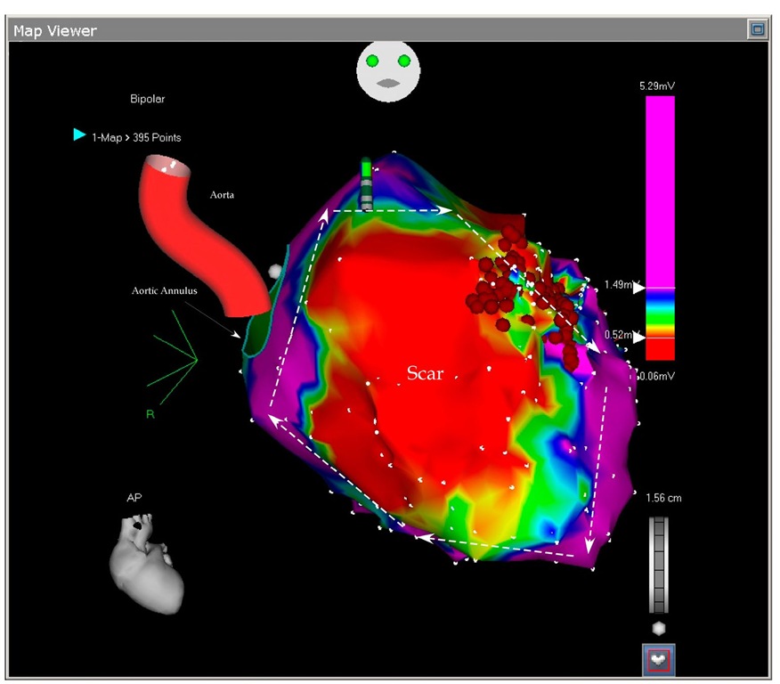
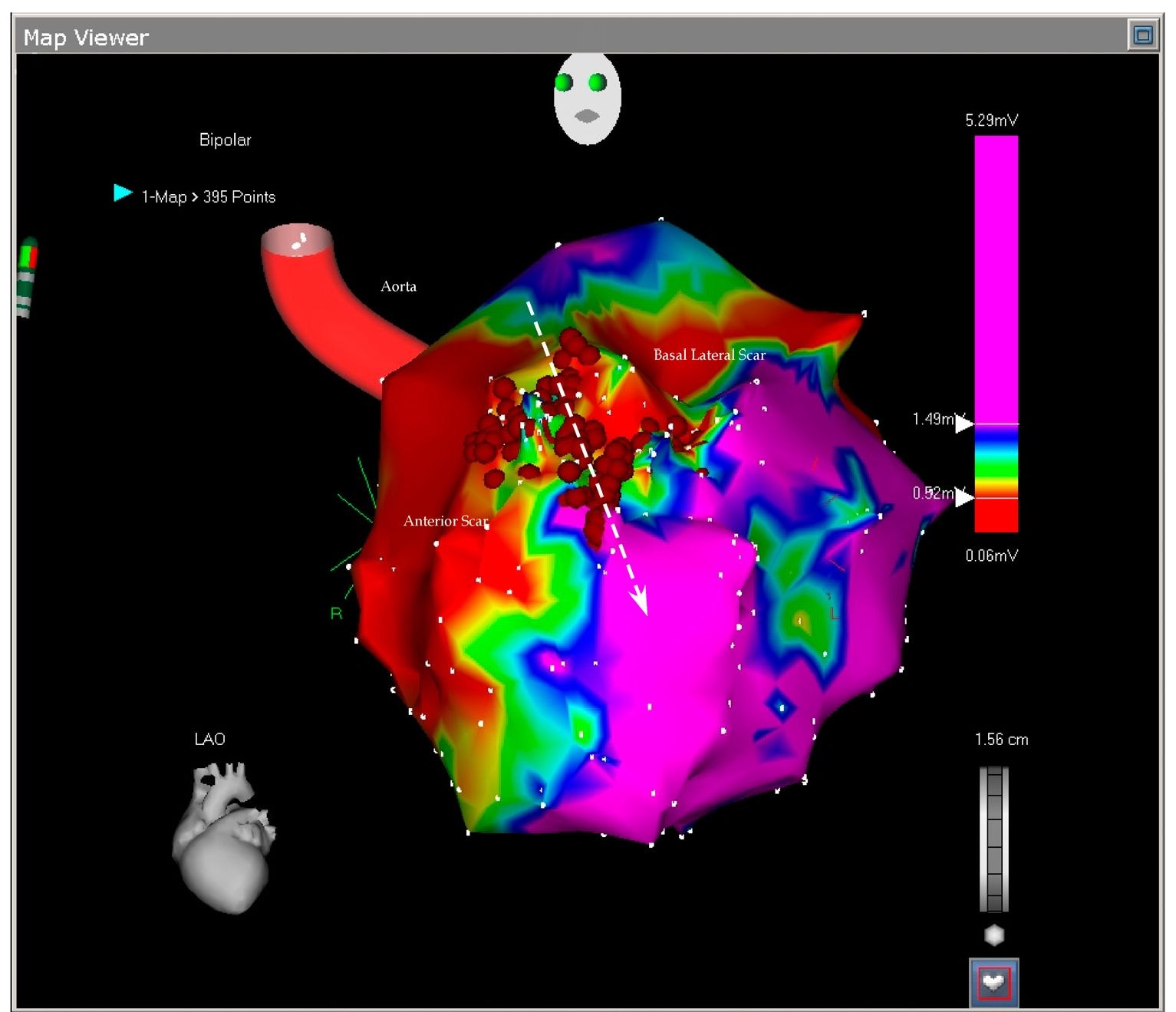
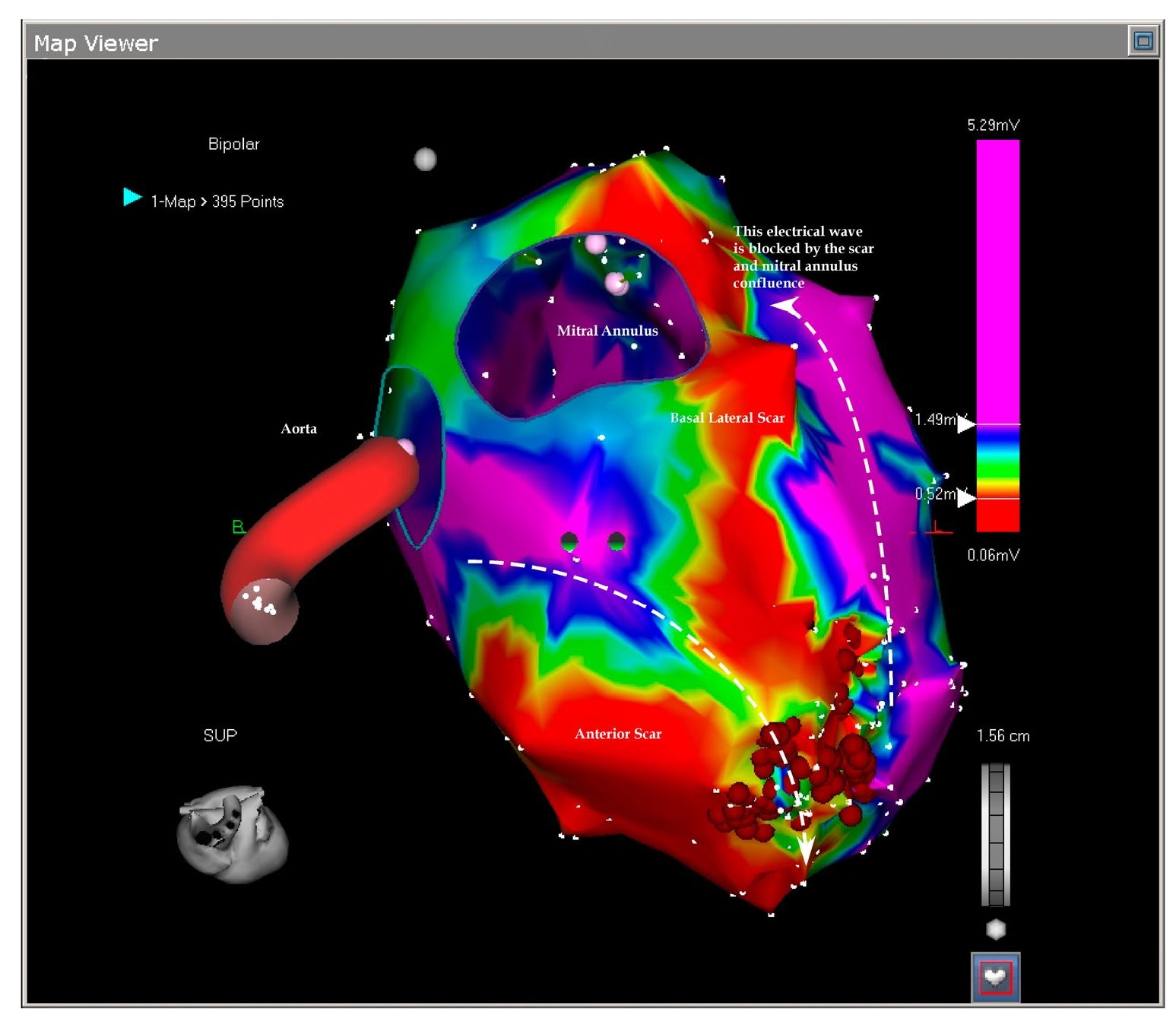
The flowing pictures exemplify the scars and the ablation (Figures 7.1, 7.2 and 7.3) The tachycardia has become not inducible after the ablation and during the 1 year follow-up since the ablation the patient was free of ICD therapies. As we can see, in this case a clear delineation of the reentry circle was revealed by the scar mapping without an intend to map the activation. Scar mapping is the option when the patient cannot tolerate the tachycardia (Marchlinski FE et al, 2000; Sra J et al, 2001). A narrow conduction tissue in the scar serves the tachycardia (Figure 7.2 and 7.3). The strategy is to block this tissue, however it is important to connect the scar to a non-conducting structure like valve annulus, otherwise the ablation will only increase the reentry circle and may render the tachycardia more incessant. In our patient the smaller scar was already connected to the mitral annulus (Figure 7.3) leaving the only possible reentry circle around the large scar and the target of the ablation the narrow myocardial strip in between them. This patient presents an ideal ablatable reentry circle. Eliminating the conduction only on a single possible pathway eliminates also the VT substrates and the patient continues to be without ICD therapy for one year. Identification of the channel was crucial in this procedure and is discussed in recent published literature (Arenal A et al, 2004; Hsia HH et al, 2006).
Fig. 7.1. The picture shows the antero-posterior projection of the enlarged left ventricle with a large scar on almost all the anterior wall. Any voltage bellow 0.5 mV (red color) was considered scar and any voltage above 1.5 mV were considered normal myocardium (purple color). In between them three transitional tissues are collared in yellow, green and blue. No tissue penetrated the scar and no central pathways could be mapped. The arrows show the large reentry cycle around the scar. Normal myocardium is around the scar and constitutes the reentry circle. The ablation points (red dots) block the isthmus between two scars.
Fig. 7.2. The picture shows the antero-lateral projection of the left ventricle. In this voltage mapping two scars are evident: the large anterior scar and a smaller basal lateral scar. The scars delineate in between them a slowly conducting myocardial tissue called isthmus (arrow). The isthmus is blocked by the ablation points. As we will see in the next picture, the basal scar is extending until the mitral annulus the reason why the reentry could not be closed around it.
Fig. 7.3. This picture shows the superior projection of the left ventricle with the aortic and mitral annuli. The basal lateral scar is confluent with the mitral ring and this confluence prevents closure of the reentry around this lateral scar leaving only the anterior scar open to permit the reentry. The ablation blocked the isthmus leaving the tachycardia non inducible.
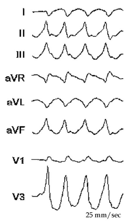
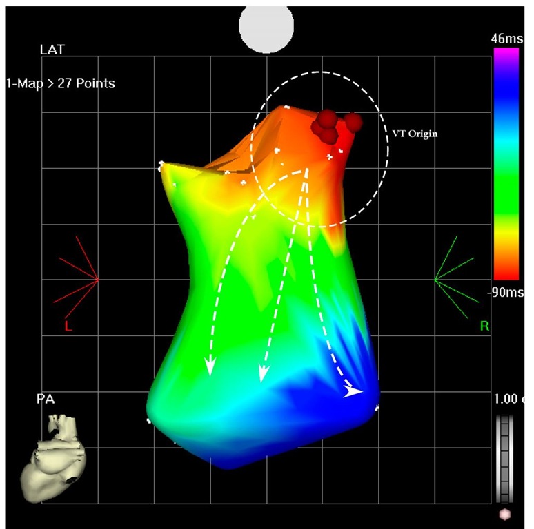
Scar ablation is an accepted approach to ablate ventricular tachycardia. Electromagnetic mapping is indispensable in delineating the scar and magnetic resonance imaging (MRI), three-dimensional computer topographies (CT) and positron emission topographies combined with CT (PET/CT) pictures may enhance it and makes possible evaluation of the exact trans-mural dispersion (Codreanu A et al, 2008; Dickfeld T et al, 2008, Tian J et al. 2010). The second patient is AG; 61-year-old man with dilated cardiomyopathy, sustained ventricular tachycardia and was referred for CRTD (cardiac resynchronization therapy-defibrillator) implantation. Interestingly, during the implantation, at the left lead pacing threshold measurement, the patient developed ventricular tachycardia. This suggested a tachycardia focus near the pacing area in the left basal posterior-lateral wall. After the implantation he developed frequent episodes of VT not suppressed by adjuvant medical treatment with amiodarone and mexiletine (Figure 7.4). For this reason he was taken to the electrophysiology laboratory and the left ventricle was mapped during ventricular tachycardia (Figure 7.5 and 7.6). Only a partial mapping was needed (overall 27 points) and the tachycardia origin was located on the basal posterior wall (Figure 7.6), just like suggested by the induction during the implantation. After 4 radiofrequency application on this site the tachycardia terminated and has become non inducible. Of note, the ECG (Figure 7.4 and 7.5) suggested the basal posterior location of the origin and the QRS during the tachycardia had RBBB (Right Bundle Brunch Block), inferior and rightward axis (Figure 7.4 and 7.5).
Fig. 7.4. The clinical VT in non-sustained form, but with the same morphology of RBBB, inferior and rightward axis
Fig. 7.5. The figure shows the ECG of the VT during the ablation. This VT had RBBB configuration and inferior and rightward axis. This configuration is suggesting a left ventricular VT with the origin in the basal area.
Fig. 7.6. The picture shows the potero-anterior projection of a part of the left ventricle during the VT. The earliest points are located on the basal posterior wall (red area) and the VT is propagated to the apical are as shown by the arrows (blue area). Ablation in this area terminated the VT and rendered it non-inducible.
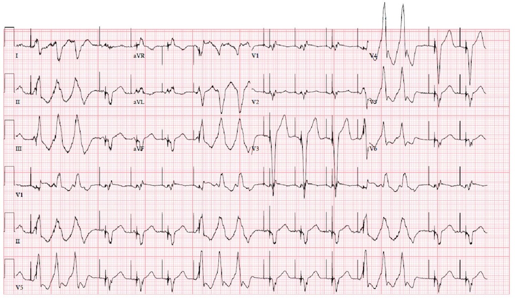
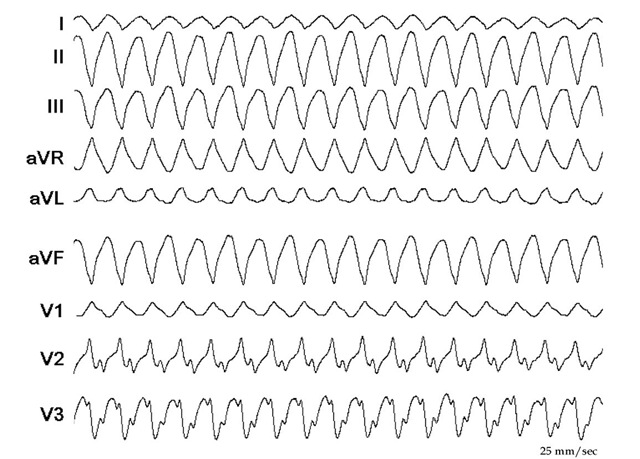
Fig. 7.7. The figure shows the ECG of the second VT during the ablation two weeks after the first one. The QRS has an RBBB configuration and superior axis. When compared with the first VT (Figure 7.5), the rightward axis is less expressed (L1 compared in the two ECGs, and AVL in the first ECG is negative and in the second is positive). There are also differences in the chest leads available (V3 is strongly positive in the first VT and clearly negative in the second VT). The rates of the VTs are similar.
Although the ablation was successful as exemplified by the previous pictures, the patient presented after two weeks with a second VT (Figure 7.7). He was taken again to the electrophysiology laboratory and the VT was mapped, again with CARTO (Figure 7.8). This time the VT had an RBBB configuration and superior axis! (Figure 7.7)
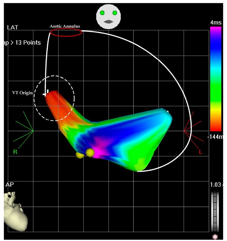
It was evident that the two VTs are not coming from the same area and again a limited map was completed (to avoid hemodynamic compromise during prolonged mapping). As Figure 7.8 exemplifies, the second VT originated from the apical septum. This are was ablated (Figure 7.9) and interestingly, after the ablation at the earliest point the tachycardia terminated, but was reinduced. This time the second ablation site at this procedure was more inferior, but after termination of the VT by the ablation, it has become noninducible.
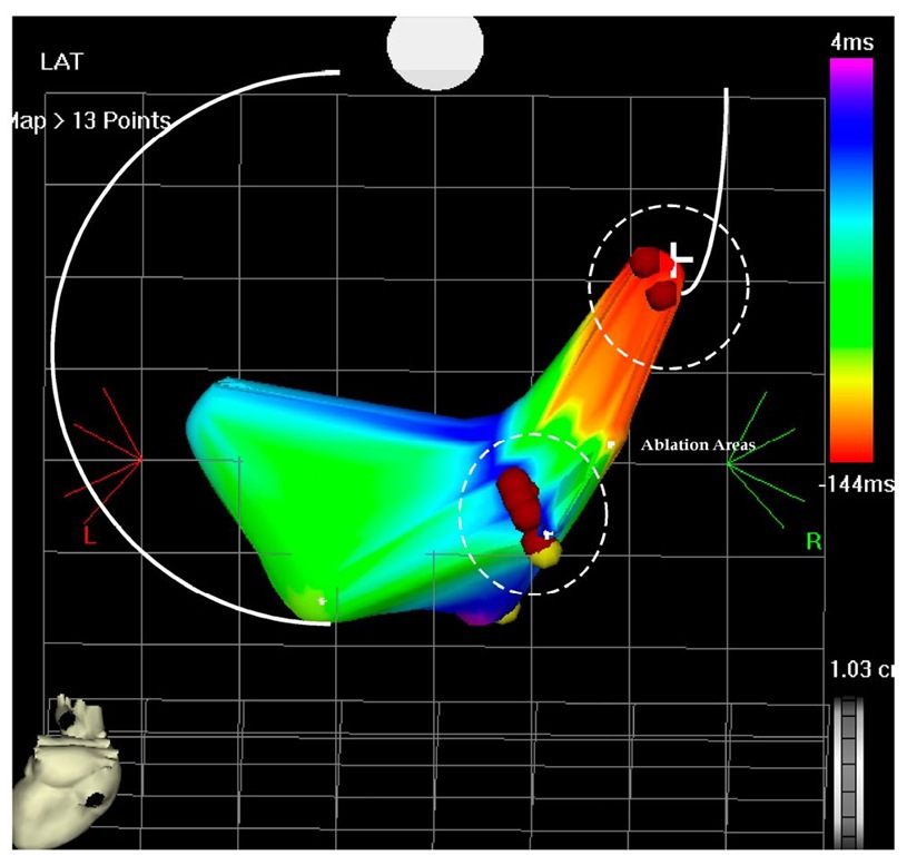
Fig. 7.8. The picture shows an antero-posterior projection of the left ventricular flow map during VT at the second ablation procedure. The left ventricular perimeter is shown with the white lines, including the aortic annulus. The earliest points are originating on the septal area and propagate in the anterior and posterior wall. There is collision on the inferior wall (pink color) and is tagged. The earliest points are -144 msec before the reference catheter in the right ventricle and the collision is 4 msec after the reference catheter.
Fig. 7.9. The picture shows the flow map of the left ventricle in postero-anterior projection. Two areas had to be ablated to terminate the VT, first the higher area and earliest one was ablated than the second more inferior are which has become early (not shown) and finally terminated the VT and left it non-inducible.
At the end of the second ablation procedure a very fast VT (200 msec cycle length) was induced requiring DC shock termination (through the implanted ICD which was immediately activated). Two years after the second ablation the patient was free of any ICD therapy. Only rare non-sustained VT was stored by the ICD. In this patient we made several clinical decisions and observations during and around the ablation procedures:
1. The left ventricle mapping was not completed, was quickly achieved and culminated with ablation
2. Propagation mapping was done as this patient has dilated cardiomyopathy and no discrete scar can be mapped
3. Although the ICD was deactivated during the procedure to prevent early termination of the VT during the mapping, it was immediately activated with the induction of the rapid VT (200 msec cycle length- ventricular flutter)
4. The rapid VT-ventricular flutter was not clinical as was not recorded by the ICD during the long follow-up.
5. The proarrhythmic effect of biventricular pacing, well known from the current literature (Nayak HM et al, 2008; Gasparini M et al, 2008, Nordbeck P et al, 2010) CH was a 59-year-old patient with a large anterior wall myocardial infarction, ventricular tachycardia and implantable defibrillator.
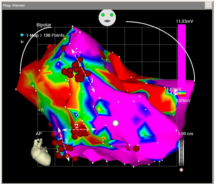
Fig. 7.10. The picture shows the extremely enlarged left ventricle, scar mapping and multiple isthmuses ablation (3 shown on this antero-posterior projection). All the procedure was completed during sinus rhythm, without ventricular pacing. The defibrillator was deactivated during the procedure.
The defibrillator was upgraded to CRTD. Two years after the upgrading, he presented with "VT storm" (more than 150 episodes of VT, majority treated with overdrive pacing and two of them with ICD shock). As medical treatment was not effective and the tachycardia has become resistant to overdrive pacing (including pacing from the RV lead, LV lead and biventricular), he was taken to the electrophysiology laboratory for catheter ablation. It was understood that no mapping during the VT can be completed because the hemodynamic imbalance. Scar mapping was attempted. The left ventricle was extremely enlarged and no catheter was available to complete to basal area mapping. After the ablation the VT frequency was significantly reduced, but not completely abolished and the patient had ventricular assist device implantation, but not survived until appropriate donor heart was available for him.
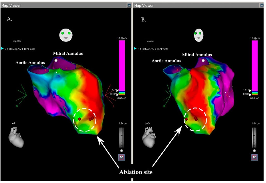
BN is a 75 year-old-man with a history of a large anterior infarction at the end of 1980′s. He was treated with intravenous Streptokinase and despite apparent reperfusion the laboratory tests suggested a large infarction. In the early 1990′s he developed aborted sudden cardiac death and a defibrillator was implanted. Occasionally, he had successfully treated episodes of ventricular tachycardia and was resolved with adjuvant amiodarone treatment. In 2008 the defibrillator was upgraded to cardiac resynchronization therapy-defibrillator (CRT-D). Recently he was admitted with incessant tachycardia with a rate between 135-140 beats per minute with relative hemodynamic stability. No medical treatment could suppress the tachycardia, including amiodarone reloading, additional mexiletine, beta-blockers and carvedilol. A coronary angiogram revealed no new coronary lesions and no target for revascularization. As the tachycardia was still incessant, the patient was taken to the electrophysiology laboratory for an ablation attempt. The left ventricle was approached through the aortic valve and the left ventricle was mapped using the fast map technique. The patient was all this time in his slow ventricular tachycardia. As evident in Figure 7.11, the left ventricle is enlarged with a large apical aneurysm and a large scar on the antero-lateral wall. The origin of the tachycardia was in the apical area at the border of the large scar (Figure 7.11). Ablation in this site terminated the tachycardia and was returned to the Cardiology Ward in sinus rhythm.
Fig. 7.11. The picture shows the voltage mapping of the left ventricle in two projections: A. antero-posterior; B. left anterior oblique; the ventricle is enlarged with a large apical aneurysm and a large antero-lateral scar. The ablation site is shown in both projections and the ablation was completed during incessant ventricular tachycardia (135 BPM) and propagation mapping. With the two lateral applications the tachycardia terminated spontaneously.
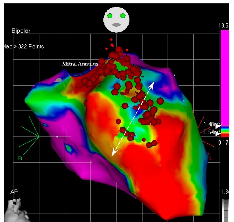
Although the tachycardia was not anymore incessant, the patient still had episodes of tachycardia at a faster rate (150-160 beats per minute). As this tachycardia was not tolerated, he was returned to the electrophysiology laboratory for a "scar ablation". This time the tachycardia was not induced and the mapping was completed in sinus rhythm (paced rhythm). Using slightly different definitions (scar in the first mapping was defined as <0.18 mV and during the second mapping as <0.54 mV), a large golf of myocardial tissue was revealed in the anterior basal area (Figure 7.12). This area was isolated from the surrounding normal tissue and the ablation area was continued until the mitral annulus to avoid any possible large reentry around the whole scar. Although the endocardial surface was completely blocked, the tachycardia was still inducible with impression of multiple breakthrough points suggesting epicardial origin. However, no real mapping could be completed because the hemodynamic instability during the VT. For this reason, he was scheduled for an epicardial ablation. During the epicardial mapping the origin of the VT was on the apical area and wide area ablation terminated the tachycardia. This epicardial site was almost the same with the successful site during the first mapping. During 3 months follow up the defibrillator recorded and stored only 4 episodes of VT successfully treated with overdrive pacing and not recalled by the patient. He continued the combination of amiodarone and carvedilol treatment. This patient also exemplifies the presence of multiple VT foci in a patient with ischemic cardiomyopathy and a large post myocardial infarction scar.
Fig. 7.12. The picture shows the mapping during the second ablation attempt. This is an antero-posterior projection of the left ventricular voltage mapping. The normal tissue was defined as >1.5 mV (like in Figure 6.11), but the scar was defined as <0.5 mV. A large invagination of myocardium into the basal scar was revealed and ablated.
In this patient, with poor left ventricular function and resynchronization therapy, a combined endocardial focal ablation, scar ablation and finally epicardial ablation completed the procedure and achieved an acceptable clinical outcome. The electro-anatomic mapping exemplifies the complexity of the ablation in this patient, and it was possible only using this advanced mapping.
Four patients were presented, each one with a different condition and different mapping. The first patient had a well-defined scar with a clear narrow strip of myocardium dividing it into a large scar and a smaller basal scar limited by the mitral annulus. The second patient has dilated cardiomyopathy without discrete scar and two different foci ablated in two consecutive procedures. The third patient had an extreme ischemic cardiomyopathy, with uncontrollable ventricular tachycardia storm and labile hemodynamic condition. Only scar ablation was possible, because the extremely dilated left ventricle. The fours patient had an enlarged left ventricle, with a large apical aneurysm. The same patient has endocardial focal ablation, scar ablation and finally epicardial ablation.
