23.6.
Wheel Balancing
For smooth rotation of the wheel and tyre assembly without causing its own vibrations, the wheel assembly must be in a state of dynamic balance. Factors responsible for an imbalance of the mass distribution around the wheel are as follows.
(i) Tyre moulding may not be fitted concentric on the wheel rim.
(ii) Wheel with lateral run out or buckled wheel rim.
(Hi) Tyre walls, crown tread thickness may be non-uniform around the carcass as a result of manufacturing defect.
(iv) Wheel lock may produce excessive tread wear during braking over a relatively small region of the tyre.
(v) Side wall may scrape the curb causing excessive wear on one side of the tyre.
(vi) Over or under inflation of tyre may cause uneven wear across the tread.
(vii) Incorrect assembly of tyre on wheel relative to valve.
Single or combination of above factors may cause uneven mass concentration (or lack of mass) about the wheel, so that one segment of the wheel and tyre becomes lighter and consequently the portion diametrically opposite to it becomes heavier. When the heavier regions of the wheel and tyre assembly revolve cause centrifugal force, which exerts an outward rotating pull on the support axis (the axle or stub axle) and bearings. The magnitude of this outward pull is directly proportional to the cut of balance mass, the square of the wheel rotational speed, and inversely proportional to the radius at which the mass is concentrated from its axis of rotation.
![]()
where, F = centrifugal force, N
m = out of balance mass, kg
V = linear wheel speed, m/s
and R = radius at which mass is concentrated from the axis of rotation, m
Example 23.1. If a 100 g of rubber tread has been removed from a portion of the tyre tread 250 mm from the center of rotation, and when the wheel has reached a speed of 160 km/h then find, (a) angular speed of wheel in revolution per minute, and (b) centrifugal force.
Solution.

This example demonstrates that when a vehicle with a typical wheel size for a car is travelling at a speed of 160 km/h, a lOOg imbalance of the tyre produces a radial outward pull on the wheel axis of 790 N.
A heavy spot on the tyre when revolving accelerates from zero to a maximum velocity for half a revolution and then decelerates to zero velocity in the second half of the revolution. As this spot has mass and its velocity changes, a varying force acts on it in a tangential direction. Consequently as the wheel moves forwards, the direction of the inertia pull caused by this heavy spot constantly changes. The greatest reaction experienced on the wheel occurs for a short time when the heavy spot decelerates downwards to ground level, momentarily stops, changes its direction and accelerates upwards. Therefore, at the end of each cycle and the beginning of the next there is a tendency to push down and then lift up the tyre from the ground. Although this effect may be insignificant at vary low speeds of the vehicle, but as the speed increases the magnitude of the accelerating force rises, which produces the periodic bump and bounce or jerking response of the tyre.
The balancing of rotating masses can be considered in two stages. Firstly the static balance in one plane of revolution, and secondly the dynamic balance in more than one plane of revolution.
23.6.1.
Static Balance
The static wheel imbalance is best understood by mounting a wheel and tyre assembly on the hub of a wheel balancing machine. The assembly is then spun around by hand and released. The wheel spins a few times depending upon the momentum gained, before it stops momentarily and then starts to oscillate to and fro with decreasing amplitude until it comes to rest. If the lowest point of the tyre is marked with a chalk and is now turned in one direction to certain angle and then released, it immediately commences a to and fro oscillatory motion, until coming to rest with the chalk mark at the lowest point. This illustrates that the heaviest part of the wheel assembly always gravitates to the lowest position. A small magnetic weight, equivalent to the out of balance mass, is placed on the wheel rim diametrically opposite the heavy side of the wheel. Now if the wheel is rotated to any other position, it remains at rest in that position. However, if there is still a slight movement of the wheel on its own, then the magnetic weight attached is too small, or if the wheel oscillates faster than before the weight is too large. This process of either adding or reducing the amount of weight placed opposite the heavy side of wheel and then moving the wheel round about a quarter of a turn to observe if the wheel tries to rotate on its own is a simple and effective technique used to check and correct any wheel
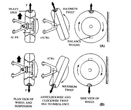
Fig. 23.24. Illustration of static wheel imbalance.
imbalance on one plane. Once the correct balancing weight has been obtained, the magnetic weight is replaced with a clip-in weight of similar mass. With experience this trial and error method of statically balancing the wheel can be quick.
As a statically unbalanced wheel and tyre, rotates on a fixed circular path around its axis (Fig. 23.24), the heavy side of the wheel pulls radially outwards due to the centrifugal force. In case if the swivel pins and the centre of the unbalanced mass are offset to each other and if the heavy spot is in the horizontal plane pointing towards the front of the vehicle, then a moment of force is produced (M = FR), which tends to twist the stub axle and wheel assembly anticlokwise about the swivel pins (Fig. 23.24A). As the wheel rolls forward a further half turn, the heavy spot now faces towards the rear so that the stub axle and wheel assembly tries to swivel in the opposite direction (clockwise) (Fig. 23.24B). Therefore with a statically unbalanced tyre, the stub axle twists about its pivot every time the heavier side of the wheel completes half a revolution between the extreme points in the horizontal plane. The oscillations thus produced are transmitted in the form of tremors to the steering wheel. The frequency and magnitude of this tremor increases with rise of vehicles speed. When the swivel pin or king pin has excessive wear, the stub axle tends to move vertically up or down on its supporting joints. This may convey vibrations to the body through the suspension, which can be critical if allowed to resonate with possibly the unsprung or sprung parts of the vehicle.
23.6.2.
Dynamic Balance
If a driven drum is made to engage the tread of the tyre so that the wheel is spun through a speed range then the wheel is likely to develop a violent wobble, which peaks at some point and then decreases as the wheel speed rises.
The balance weight may be placed correctly opposite the heavy spot of the tyre, but on the wheel rim may be in a different rotational plane to that of the original out of balance mass. Consequently the tyre heavy spots pull outwards in one plane while the balance weight of the
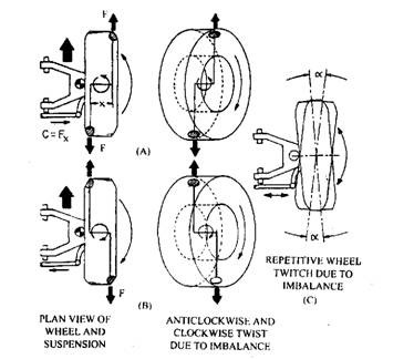
Fig. 23.25. Illustration of dynamic wheel imbalance.
wheel rim pulls radially outwards in a second plane. As a result a rocking couple is produced, which causes the wheel to wobble. The magnitude of this couple is proportional to the product of centrifugal force acting through one of the masses and the distance between the opposing forces (C = FX).
Figure 23.25A, B and C illustrates the effects of the offset statically balanced masses. When the heavy spot and balancing weight are horizontal (Fig. 23.25A) the mass on the outside of the wheel points in the forward direction of the vehicle and the mass on the inside of the wheel points towards the rear so that the wheel tends to twist in an anti-clockwise direction about the swivel pins. If the wheel is rotated further through 180 degrees, the weights again are horizontal but this time the weights have interchanged their positions. Therefore, the direction of the unbalanced rocking couple is now changed to a clockwise one. The wheel, thus, rocks in both a clockwise and anticlock-wise direction during its every revolution causing the steering wheel to jerk from side to side (Fig. 23.25C). It may be noted that when the masses move to a vertical position relative to the ground, the swivel pins constrain the rocking couple so that no movement occurs unless the swivel ball joints or king pins are excessively worn.
The magnitude of wheel twitching about the swivel pins steadily increases with rise in wheel speed with static unbalanced wheels. In case of dynaiuic imbalance, the magnitude of wheel twitching increases to a maximum and then decreases with further increase of wheel speed (Fig. 23.26). Therefore a dynamic unbalanced wheel can be driven on road without noticing any appreciable instability at speeds, which fall on either side of the critical period of oscillation
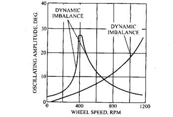
Fig. 23.26. Variation of oscillating amplitude with wheel speed for both static and dynamic imbalance.
(maximum amplitude). However, if the wheel is driven within the narrow critical speed range violent wheel wobble results. Any looseness in the swivel pins or steering linkage ball joints with unbalanced tyres promotes excessive wheel twitch or wobble, causing not only the steering wheel vibrations, but also heavy tyre tread scrub and wear.
23.6.3.
Methods of Balancing Wheels
Wheel balancing machines can be on- or off-vehicle type. The on-vehicle wheel balancer has the advantage of balancing the complete wheel assembly, which includes the hub, brake disc or drum, wheel and tyre. In this method, however, the transmission drive line does not allow the wheel hub to spin freely, which is essential for measuring the imbalance of any rotating mass.
Off-vehicle balancing machines require removal of the wheel from the hub and mounting on a rotating spindle of the balancing equipment.
Balancing Statically and Dynamically in Two Separate Planes.
Balancing Machine.
The wheel to be balanced is mounted on the spindle of the main-shaft, which is driven by an electric motor. This machine uses a self-aligning ball bearing at the wheel end and is mounted rigidly to the balancing machine frame. The rear bearing is supported between a pair of stiff opposing springs, fixed to the balancing machine frame. The electric motor drives the spindle through the engagement drum, which rubs hard against the tyre tread of the wheel assembly (Fig. 23.27). During spinning, as the wheel and tyre assembly commences to wobble about the self-aligning bearing, the restraining springs that supports the second bearing absorb the out of balance forces as well as the deflection of the main shaft and spindle.
An electromagnetic moving coil vibration transducer is mounted vertically between the second bearing and the machine frame. During wobbling of the wheel assembly, the armature rod placed at the centre of the transducer coil moves in and out of a strong magnetic field produced by the permanent magnet, Oo that a voltage proportional to the relative movement of the rod is generated in the armature coil. The output signal from the transducer is fed into a compensating network, which converts the signals directly into the required balance weight. These modified, but still very weak, electrical signals are passed through a filter to eliminate unwanted side interference and then are amplified to activate the stroboscope device and the weight indicator meter.
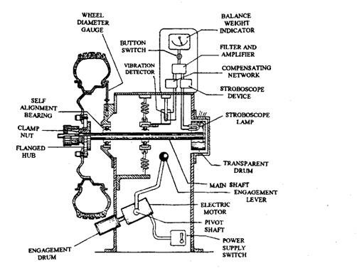
Fig. 23.27. Wheel balancing machine which balances statically and dynamically in two different planes.
The weight indicator meter is calibrated to indicate the size of the weight to be added to the plane of balance, in this case the outside of the wheel rim in the left hand plane. The stroboscope determines the angular phase of the balance weight on the wheel. To obtain this phase the sinusoidal voltage is converted into a sharply defined bright flash of light in the stroboscope lamp. A rotating numbered transparent drum is illuminated by the stroboscope flash and the number, which appears on the top of the drum relates to the phase position of the required balance weight.
Mounting of the Wheel.
After mounting the wheel onto the flanged multi-hole steel plate (Fig. 23.27), the wheel stud holes are aligned with corresponding threaded holes in the flange plate and then are screwed onto the wheel studs provided. The wheel hub assembly is slid along the spindle until the inside of the wheel rim just touches the adjustable distance rod and then the hub is locked to the spindle through the sleeve nut. The positioning of the wheel assembly relative to the supporting self-aligning bearing is specifically important because the inside wheel rim remains in the same rotating plane as the centre of the bearing. This eliminates the possibility of the formation of any couple when the balance weights were attached to the inside of the wheel rim, as there is no offset.
Dynamic Balance Setting.
For dynamic balancing, the power is switched on and the drive roller lever is pulled until the roller is in contact with the tyre so that the wheel is revolved. Once maximum speed of the wheel is reached, the lever is pushed so that the roller is freed from the tyre. In case of unbalanced wheel assembly, the wheel passes through a violent period of wobble and then it becomes steady again as the speed falls. While the wheel is vibrating, the magnitude and position of the imbalance can be observed from the meter and the stroboscope disc aperture respectively. A correction factor, provide for the different wheel diameters, must be multiplied by the meter reading to give the actual balance weight. The nearest size of balance weight to that calculated is selected, and then the wheel is rotated by hand to the number constantly shown on the stroboscope disc when the wheel was spinning. Finally the appropriate balance weight is attached to the top of the wheel on the outside (away from the machine). This balances the outer half of the wheel (Fig. 23.27).
Static Balancing Setting.
To achieve static balance, the wheel is allowed to settle naturally and to come to rest with the heaviest point at bottom dead centre. A magnetic weight (say 50 grammes is placed on the inside rim at top dead centre and the wheel is turned a quarter of a revolution. If the magnetic weight is more, the weighted side naturally gravitates towards the bottom but if it is insufficient, the weight rises slowly to the top. The procedure is repeated until the wheel has no tendency to rotate on its own whatever be its position. The wheel is now statically and dynamically balanced. For a quick check, the spin test for dynamic balance can be repeated. The correct static balance magnetic weight has to be replaced by a clip-on type (Fig. 23.27).
Dynamically Balancing in Two Planes.
Balancing Machine. In this machine the wheel to be balanced is mounted on the spindle of the main shaft, which is supported by a pair of spaced out ball bearings housed in a cylindrical cradle. The cradle is supported on four strain rods which have reduced diameter in their mid region (Figure 23.28). The main-shaft is driven by an electric motor through a rubberized flat belt and pulleys.
Vibration transducers of electro-mechanical moving coil type are normally used to sense the out of balance forces caused by the imbalance of the wheel assembly. The transducer uses a
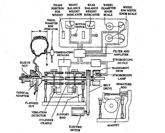
Fig. 23.28. Wheel balancing machine which dynamically balances in two planes.
small armature rod with a light weight coil, positioned in the direction of vibration. The rod is free to move in a strong magnetic field produced by a permanent magnet. The armature rods are rigidly attached to the main shaft and bearing cradle. The armature coil due to the relative vibratory motion of the armature rod to the casing generates a voltage proportional to the relative vibrational velocity.
The output signals from the two transducers are fed into a compensating network and then into the selector switch. The out puts from the compensating network are proportional to the required balance weights in the left and right hand balancing planes respectively. The output voltages from the selector switch are filtered to eliminate unwanted frequency components and are amplified to operate the stroboscope device and both weight indicating meters. These calibrated meters measure the amplitude of the voltage from the transducers and indicate the actual balancing weights require in each plane. The stroboscope device converts the sinusoidal voltage into a sharply defined pulse which occurs at the same predetermined point in every cycle. This pulse is converted into a very bright flash of light in the stroboscope lamp when focussed on the rotating numbered transparent drum and one number appears on the top of the apparently stationary surface. The number is a measure of the relative phase position of the voltage, which indicates the position of the required balance weight. Balancing machines of this type usually measure and provide correction for both static and dynamic imbalnace of the wheel with respect to both the outer and inner wheel rim rotating planes.
Dynamic Balance Setting in Two Planes.
The wheel is mounted over the spindle and the conical adaptor is slide towards the wheel so that its taper enters the central hold of the wheel. The sleeve nut is screwed to centralize and wedge the wheel against the flanged hub (Fig. 23.28). Any existing balance weight is removed and the wheel is cleaned with a brush. The wheel diameter and wheel rim width, the two basic wheel dimensions, are then programmed into the electronic network circuit. This is carried out by simply moving the wheel diameter indicator probe against the inside of the wheel rim, which provides the wheel diameter and also measuring the wheel width with a caliper gauge. These measurements are then set by rotating the respective potentiometer knob on the display consul to these dimensions. Now electronic network is corrected for changes in the centrifugal force and rocking couples due to variation in wheel sizes.
The electric motor is started to rotate the main-shaft through the drive belt and spin the wheel assembly under test. The outer rim weight indicator meter switch is pressed to measure the state of wheel balance in the outer wheel rim plane of rotation. The meter pointer aligns on the scale indicating the balance weight required in grammes. The stroboscope window indicates a number corresponding to the wheel position for attaching a balance weight. After ascertaining balance weight size and angular position, the wheel assembly is brought to a standstill.
The wheel is now rotated by hand until the number previously observed through the stroboscope window again appears. The selected size of balance weight is now attached to the top of the outer wheel rim.
The whole procedure of spinning the wheel assembly is then repeated but this time the inner rim weight indicator button is pressed. The balance weight reading and the phase position of the wheel are observed for the inner rim rotating plane. Again the wheel is braked and then turned by hand to the correct phase position indicated by the stroboscope number. Finally the required balance weight is attached to the inner wheel rim at the top of the wheel.
