20.12.
Valve and Cylinder Head Servicing
Valve Condition.
The valves, after removal from the engine, should be examined carefully to analyse the causes of their failure..Valve failure results from misaligned valve seating, excessive tempera-

Fig. 20.103. Valve face peening.
ture, high velocity seating, and high mileage. All these factors are normally interrelated. Valves failure may also result from exceeding their operating limits. The cause of the failure should be rectified so that new or reconditioned valves can perform satisfactorily.
Valve Seating.
Valve burning (Fig. 20.100) and value guttering (Fig. 20.101) are common types of valve failure resulting from poor seating, which allows the high-temperature and high-pressure gases to leak between the valve and seat. Poor seating occurs due to insufficient valve lash, hard carbon deposits, valve stem deposits, excessive valve stem-to-guide clearances, or out-of-squareness between the valve guide and seat.
Insufficient valve lash may be due to improper valve lash adjustment on solid lifter systems and due to collapsed hydraulic lifters. The clearance is also reduced from valve head cupping (Fig. 20.102) or valve face-seating wear.
Hard carbon deposits loosen from the combustion chamber sticks between the valve face and seat so that the valve is held slightly off its seat. This reduces valve cooling through the seat and also allows some of the combustion gases to escape. Due to continued pounding on hard carbon particles, the valve face exhibits a peened appearance (Fig. 20.103). Positive valve rotors help to combat the effects of deposits and thereby prevent valve burning.
Fuel and oil on the hot valve surface break down and become hard carbon and varnish deposits, which build-up on the valve stem (Fig. 20.104). These deposits cause the valve to stick in the guide so the valve does not seat completely due which the valve face burns.
The valve with excess steam clearance, too much oil goes down the stem, which increases deposits. This is more critical on intake valves. Moreover, wide valve guide clearance causes the valve to cock, specifically with rocker arm action. Continued cocking does not allow the valve to seat properly so that leakage occurs, burning the valve face.
Sometimes, the cylinder head warps as it is tightened to the block deck during assembly. Also, heating and cooling develop
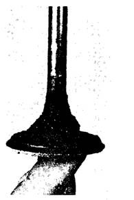
Fig. 20.104. Heavy carbon build-up on an intake valve.

Fig. 20.105. Valves broken by thermal shock.
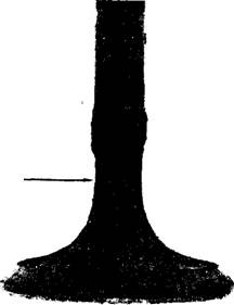
Fig. 20.106. Valve stem necking.
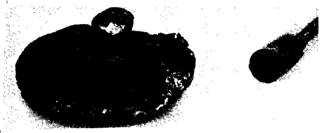
Fig. 20.107. Valve stem breakage due to misalignment.
warpage. If head warpage causes valve guide and seat misalignment, the valve cannot seat properly.
Excessive Temperature. High valve temperature develops if the valve does not seat properly; although it can also occur even when the valve is seating
Eroperly. Cooling system passages in the ead may be partially blocked by casting imperfections or due to deposits built up
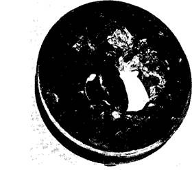
Fig. 20.108. Valve breakage due to high velocity seating that broke the piston.
from the coolant. Extremely high temperatures produced by pre-ignition and detonation develop a very rapid increase in temperature causing uneven heating and giving a thermal shock to the valve. The shock frequently develops radial cracks in the valve. These cracks permit the combustion gases to escape and gutter the valve face. If the radial cracks intersect, a pie-shaped piece breaks from the valve head (Fig. 20.105). The rapid cycling from full throttle to closed throttle and back again also produces thermal shock.
High engine speeds are associated with high gas velocities. The high velocity exhaust gas impinges on the valve stem, and tends to erode the metal. The gases being corrosive also tend to corrode the valve stem. The corrosion rate doubles for each 14 K increase in temperature. Erosion and corrosion of the valve stem cause necking (Fig. ’20.106) that weakens the stem leading to breakage.
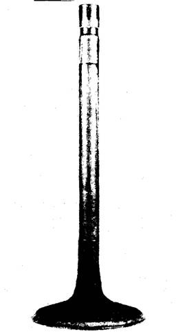
Fig. 20.109. Badly worn valve stem.
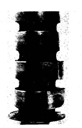
Fig. 20.110. Edge wear on a cam.
Misaligned Valve Seats. Each time the valve closes with the improper valve-to-seat alignment, the valve head must twist to seat. With excessive twisting or bending, the steam becomes fatigue so that the valve head breaks from the steam. The break appears as lines arcing around a starting point.
High Velocity Seating. High velocity seating is indicated by excessive valve face wear, valve seat recessing, and impact failure (Fig. 20.107). It can be caused by excessive lash in mechanical lifters and by collapsed hydraulic lifters so the valve hits the seat without the effect of the cam ramp to ease it onto its seat. Excessive lash may also occur due to wear of parts such as cam, lifter base, push rod ends, rocker arms, and valve tip. Weak or broken valve springs allow the valves to float away from the cam lobes so that valves are uncontrolled as they hit the seat. The normal tendency of hydraulic lifters is to pump up under these float conditions and this reduces valve impact damage.
Impact breakage may take place under the valve head or at the valve lock grooves. The break lines radiate from the starting point. The valve head normally falls into the combustion chamber and is jammed between the piston and head. In most cases, it damages the piston before the engine can be stopped (Fig. 20.108).
High Mileage. High mileage normally indicates excessive wear of the valve stem (Fig. 20.109), guide, valve face, and seat. They are usually accompanied by considerable deposits. The valves, however, still be seating and show no indication of cracks or burning.
Valve-train Condition.
Valve failure may be due to the valve-train condition, which is usually indicated as wear. Valve-train wear generally results from exceeding operating limits and from loss of lubrication.
Camshaft. Camshaft failure shows up as cam lobe failure. Lobe failure starts as small pits caused by severe edge wear (Fig. 20.110).
The lobe gradually wears during the operation of the engine until it looks like a round journal. A badly worn cam gives rise to badly worn lifters. Occasionally, the lobe chips as the result of impact damage, caused by careless handling. The camshaft condition and service have been discussed in more detail in section 20.9.
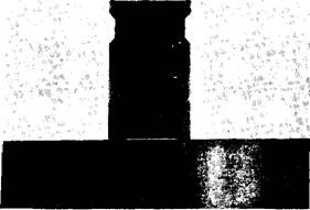
Fig. 20.111. Lifter face worn concave causing cam edge wear.
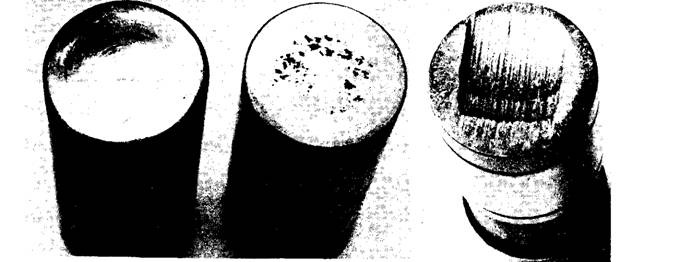
Fig. 20.112. Excessively worn lifter faces.
Lifters. Camshaft lobe failure causes the lifter face damage. Failure of the face may start with pits or with smooth wear. The face gradually becomes concave (Figs. 20.111 and 20.112). This also wears the cam. Pitted or concave lifter faces are not repairable, and hence replacement of the lifter is necessary. For maximum service life, new lifters with a new cam should be installed. A worn cam may rapidly damage new lifter faces providing a short lifter service life. Worn lifters always damage the cam.
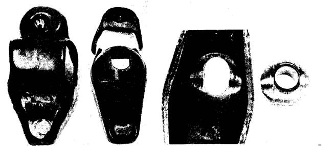
Fig. 20.113. Worn and broken rocker arms.
Hydraulic lifter parts are fitted selectively and hence cannot be interchanged between lifters. Lifters that do not have abnormal wear are disassembled and cleaned, one at a time, to prevent intermixing of parts. After reassembly, they are checked for leak-down rate. If the rate is excessive, the lifter should be replaced. The labour to clean a lifter may be more expensive than installing a new lifter.
Rocker Arms. Worn rocker shafts and matching rocker arms should be replaced. A stamped rocker arm requires replacement if its face is worn. Some of the older cast rocker arms could have their faces ground. Worn stamped rocker arms, pivot balls, or shafts should be replaced. Worn rocker arms are pictured in Fig. 20.113.
Pushrods. Failure of pushrod takes place due to lack of lubrication or from overstressing. Lack of lubrication gives rise to excessive pushrod end wear. Over-stressing causes bent pushrods. Rod bend can be detected by rolling the pushrod
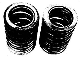
Fig. 20.114. Spring end wear from excessive rotation
across a flat surface and any wobble indicates that the rod is bent. Bent or worn pushrods must be replaced.
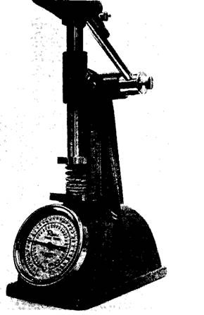
Fig. 20.116. Checking valve spring pressure.
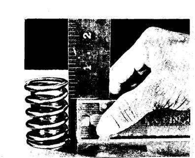
Fig. 20.115. A square being used to check valve spring squareness.
Valve Springs. Valve springs often rotate in use and become shiny on the end (Fig. 20.114). They may develop pits or take a set. Wear and pits are checked visually. Valve spring set may result in warping the spring or in loss of tension.
Valve spring warpage is checked with a square on a surface plate, and maximum out of square is 1.5 mm (Fig. 20.115). Spring tension is checked in a valve spring gauge (Fig. 20.116). The spring tension is checked at the installed length and at the valve open length. Pressure loss up to 10% is serviceable. Valve spring requires replacement if any abnormality is observed. Valve springs are inexpensive, so they are replaced when the valve system is reconditioned.
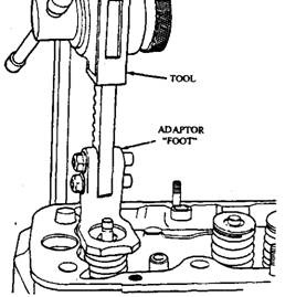
Fig. 20.117. Valve spring removal.
Valve Retainers and Locks. Valve retainers and locks are confined only to a visual inspection. Cracks, wear or any doubt on the serviceability of the retainers and locks are reasons for their replacement. If the lock or retainer fails, the valve may fall into the combustion chamber causing extensive damage.
Cylinder Head Cleaning and Distortion Measurement.
Recommendation of the manufacturer for a special head bolt removal sequence should be followed for some aluminium cylinder heads. A valve spring compressor (Fig. 20.117) should be used to remove valves and valve spring from the cylinder head.
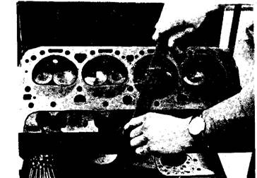
Fig. 20.118. Draw filing the head parting surface.
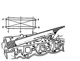
Fig. 20.119. Cylinder head distortion measurement.
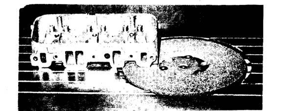
Fig. 20.120. Cylinder head grinding.
Valve and spring should be secured in proper sequence to reinstall them in their original location. Section 20.6 may be referred for engine block and cylinder head cleaning.
A circular wire brush fitted in an electric drill is conveniently used to remove hard carbon from the combustion chanjtber. The cylinder head should be perfectly cleaned prior to the measurement of the distortion. The clean head gasket surface is draw-filed flat to remove any raised portions (Fig. 20.118). A straightedge and a feeler gauge are used to measure cylinder head distortion at the locations shown in Fig. 20.119.
If the distortion is more than the manufacturer’s specifications, a small amount of metal is required to be removed from the head surface using a cylinder head grinding machine (Fig. 20.120). The top of the block is also checked for distortion in the same manner as the cylinder head.
Cylinder heads or other castings are checked for cracks. To perform the test for cracks, magnetic dust or iron fillings are spread on the cylinder head. A large electromagnet is then placed over the test area. The iron fillings fill in any cracks as they move across the surface (Fig. 20.121). Cylinder head must be thoroughly cleaned after conducting the crack test.
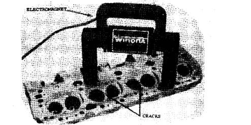
Fig. 20.121. Cylinder head crack check.
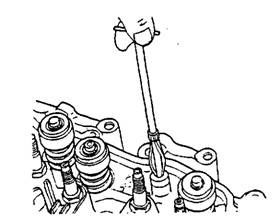
Fig. 20.122. Valve guide cleaning.
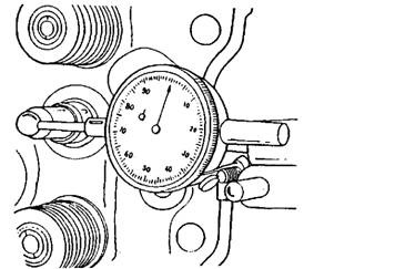
Fig. 20.123. Valve guide clearance measurement.
Valve Guide Servicing
Valves and seat areas in the cylinder head must be cleaned prior to initiating valve servicing operations. A special chuck may be used to hold the valves during their cleaning on a wire buffer. The cylinder head seat area may be cleaned with a circular wire brush driven by an electric drill. A valve guide cleaning brush should be used to clean the valve guides (Fig. 20.122).
Valve guide clearance is measured with a dial indicator (Fig. 20.123) positioned against the side of the valve stem. When the valve stem is moved horizontally, the dial indicates the valve stem-to-guide clearance. The valve stem diameter is measured with a micrometer. When the stem-to-guide clearance is excessive even if the valve stem diameter equals the manufacturer’s specifications, the guide must be replaced.
A valve guide gauge is also used to measure valve guide wear. Various sizes of probe are available to enable the gauge to measure any guide. The valve guide gauge is capable of measuring all types of guides, including cast iron, knurled, threaded, and bronze guides, and also the size and roundness of the guide at every point.
Excessive valve stem-to-guide clearance results in improper seating of the valve due to which excessive leakage of cylinder gases past the valve seat overheats the valve, causing premature valve failure. Excessive guide clearance creates a higher valve temperature because
heat cannot be transferred properly from the valve face to the stem and guide. The valve must be concentric with the guide as illustrated in Fig. 20.124 to obtain normal service of the valve. If the guides are worn cylinder vacuum draws an excessive amount of oil past the guides and into the cylinders.
Valve Guide Knurling.
A special tool that cuts a spiral groove inside the guide is used to restore valve guides to their original size. The knurling grooves hold

Fig. 20.124. Valve mechanism concenretric with guide.
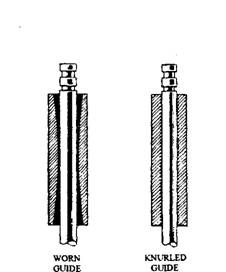
Fig. 20.125. Knurled valve guide and worn valve guide.
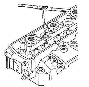
Fig. 20.126. Valve guide reamer.
a supply of oil in the guide. A worn guide and a knurled guide are shown in Fig. 20.125.
Valve Guide Reaming. A reamer is used to enlarge the guide opening. A valve with an oversized stem may be fitted in each guide to provide the specified stem-to-guide clearance. The use of a valve guide reamer is illustrated in Fig. 20.126.
Valve Guide Replacement. On cylinder heads with removable valve guides, a valve guide driver (Fig. 20.127) is used to remove the guides from the head.
The new guide may be driven into the head using the same driving tool. The original distance from the head surface to the top of the guide must be maintained on the new guides. Some guides have a clip that bottoms on the cylinder head at the correct height (Fig. 20.128) when the guide is installed.
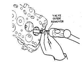
Fig. 20.127. Valve guide removal.

Fig. 20.128. Valve guide installed in a cylinder head.
Some guides from the integral part with the head. When these guides are excessively worn so that they cannot be repaired by knurling or reaming, then an integral guide-drilling machine is used to remove them. After the drilling operation, a removable guide is installed in the head.
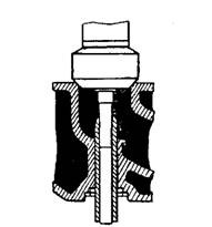
‘ Fig. 20.129. Valve seat grinding wheel and pilot.
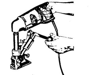
Fig. 20.130. Grinding stone dressing tool.
The integral guide-drilling machine can be both automatic and manual. For faster and more efficient guide servicing the automated machine is used. The integral guide-drilling machine
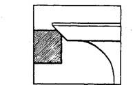
Fig. 20.131. Correct valve seat contact.
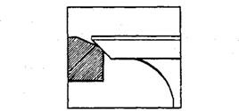
Fig. 20.132. Removing material at the top of the valve seat.
also cuts out integral valve seats.
Valve Seat Servicing.
A pilot and grinding wheel are used to grind the valve seat. The correct size of pilot is installed snugly in the valve guide, and the grinding wheel is positioned on top of the pilot (Fig, 20.129).
A seat dressing tool is used to cut the grinding stone to the correct angle before grinding the valve seat (Fig. 20.130).
An electric driver is used to rotate the grinding stone. Once the valve seat has been ground, the seat must make perfect contact with the entire circumference of the valve face. The valve face should always be larger than the seat, so that the seat can contact at the centre of the valve face (Fig. 20.131).
The seat should also be sufficiently wide for quick dissipation of heat from the valve. A too wide valve seat collects excessive amounts of carbon. The average recommended valve seat width is 1.524 mm. The valve seat must be narrowed occasionally for proper seat contact. A 15 degree grinding wheel is normally used to remove material at the top of the seat (Fig. 20.132).
When material is required to be removed from the bottom of the seat, a 60 degree grinding wheel is used. Some valve seats can be removed from the cylinder heads, while other seats are integral with the head. A puller is used to take out removable seats from the head.
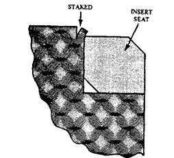
Fig. 20.133. Valve seat insert installation and staking.
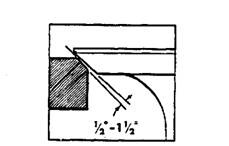
Fig. 20.134. Interface valve seat angle.
A cutting tool is used to cut out integral valve seats, so that a removable seat can be installed. The integral guide-drilling machine also cuts integral valve seat inserts. For replacement valve seat inserts must be slightly larger than the opening in the head so that they fit into the cylinder head with an interference fit. The interference fit is 0.050 to 0.101 mm for a 25.4 to 50.8 mm seat having 6.35 to 9.52 mm depth. The valve insert must be driven into the head using an insert driving tool and then staked using a chisel (Fig. 20.133).
Many engine manufacturers recommend that valve faces should contact valve seats with an interference angle (Fig. 20.134). This can be achieved by grinding a 45 degrees valve face to
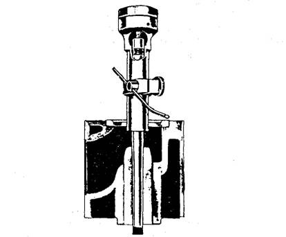
Fig. 20.135. Valve seat concentricity indicator.
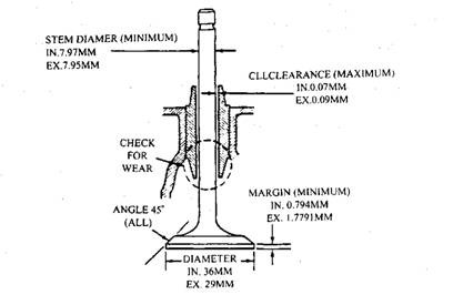
Fig. 20.136. Valve specifications.
44 degrees or 30 degrees valve face to 29 degrees, while the seats maintain the specified angle of 45 degrees or 30 degrees. An interference fit may also be obtained by grinding the seats to 46 degrees or 31 degrees. In this case also the valve faces maintain 45 degrees or 30 degrees. In Fig. 20.134, the valve has 0.5 to 1.5 degrees less interferece angle than the seat. This produces high contact pressure at the combustion chamber edge of the seat, which seals the valve and prevents leakage.
Valve seat concentricity is measured with a valve seat indicator. A dial indicator on top of the tester indicates the variations in valve seat concentricity (Fig. 20.135).
Valve Servicing.
Valve faces are ground on a valve-grinding machine. The machine manufacturer’s recommended procedure is to be followed while grinding valves faces. Always the grinding wheel is moved away from the valve before the valve is moved off the wheel. The face is ground until all irregularities are removed. After the valve has been ground, it must still maintain the specified margin. The valve margin and other specifications are provided in Fig. 20.136.
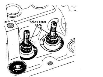
Fig. 20.138. Valve seal installation.
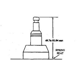
Fig. 20.137. Valve spring seat to valve tip measurement.
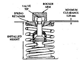
Fig. 20.139. Valve spring installed height measurement.
A too narrow valve margin overheats the valve, resulting in short valve life. The overheated valve edge may ignite the air-fuel mixture before the spark plug fires. This pre-ignition causes detonation and possible engine damage. After the grinding of the valve faces, the valve stem tips should also be ground to remove irregularities. Once stem tip grinding is over, the edge of the valve stem tip should be ground to provide a 0.793 mm chamfer.
Valve Spring Testing. Valve springs should be measured for height and squarness (Fig. 20.113). If these dimensions do not meet the manufacturer’s specifications, the valve spring should be replaced.
Valve spring tension must be checked in the spring tension tester (Fig. 20.116). The knob on the tester is set at the specified height, and the torque wrench is pulled until a click is heard. The torque wrench is read before the tester clicks. If the spring tension is weak the spring requires replacement.
The valve-tip-to-valve-spring seat dimension should be measured using an inside calliper after grinding the valve face and seat. The valve stem tip, if necessary, should be ground to provide the specified height. Figure 20.137 illustrates the valve stem height.
Prior to the installation of the valves, the stem should be well lubricated with engine oil and the valve stem seals should be installed as indicated in Fig. 20.138.
During installation of the valve spring it is to be noted that the thickest part of the coil should face the cylinder head. The valve springs, retainers, and retainer locks should be installed using the valve spring removal tool. The installed valve spring height should be measured (Fig. 20.139).
If the installed spring height is more than specified, a spacer of the specified thickness must be placed under the valve spring (Fig. 20.140).
Rocker Arm Servicing.
Rocker arm is checked for wear in the bore and on each end. The outer end of the rocker arm that contacts the valve stem is refaced on the valve-grinding machine. Rocker arm pivots or shafts are checked for excessive wear. All worn parts are replaced. The push-rods are checked for a bent condition and wear on the ends. Oil is supplied through hollow pushrods to the rocker arms on many engines. Therefore, the push-rod passages are checked to make sure that they are not obstructed.
Valve Lifter Servicing.
The valve lifter assemblies should be secured in proper sequence to install them in their original position. Many newer engines have roller-type lifters so that friction between the lifter
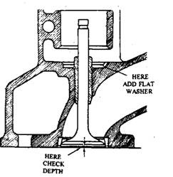
Fig. 20.140. Spacer installation to correct higher installed valve spring height.
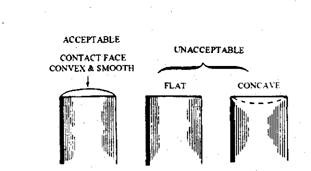
Fig. 20.141. Acceptable and unacceptable lifter bottoms.
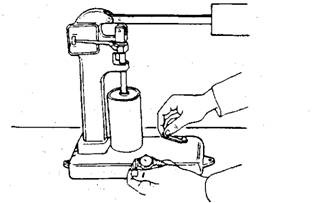
Fig. 20.142. Valve lifter leak down test.
for a bent condition and wear on the ends. Oil is supplied through hollow pushrods to the rocker arms on many engines. Therefore, the push-rod passages are checked to make sure that they are not obstructed. . ”
Valve Lifter Servicing.
The valve lifter assemblies should be secured in proper sequence to install them in their original position. Many newer engines have roller-type lifters so that friction between the lifter and the camshaft lobe is reduced. This type of lifter incorporates a retainer in the engine block to prevent lifter rotation.
Valve lifters are dissembled by removing the clip in the top of the lifter. Lifter components are washed in clean solvent, and the parts should not be interchanged from one lifter to another. All lifter components are inspected for pitting, scoring, galling, and excessive wear. The conventional lifters are checked for evidence of non-rotation. If any of these defects are present, the entire lifter must be replaced. The bottom of an acceptable lifter must be slightly convex (Fig. 20.141).
Valve lifters are tested in a leak down tester (Fig. 20.142). If the leak down time does not equal specifications, the valve lifter should be replaced.
