28.2.
Types of Brake
The two main types of friction brake are drum brake and disc brake (Fig. 28.4). In both types a fixed (non-rotating) shoe or pad rubs against a moving drum or disc. To increase the friction between the rubbing surfaces, a special friction material is attached to the fixed part. Earlier this friction material had a high content of asbestos, but its dust is injurious to health so that a safe asbestos free friction material is nowadays used.

Fig. 28.4. Types of brake.
Drum Brakes.
This internal expanding type of brake contains two shoes that are attached to a back-plate and are fixed to a stub axle or axle tube. The section of each shoe is of “T” shape. A friction lining
is riveted or bonded to the outer face of the shoe. A drive is fitted at one end of the shoe so that the shoe expands when the brake pedal is applied. In a simple brake (Fig. 28.5) a cam is used as a shoe expander, but modern systems for cars use hydraulically operated pistons for shoe expansion.
The shoe anchor is rigidly attached to the back-plate and takes the form of a large pin that passes through the shoes, or housing. The shoes butt against the anchor. Springs pull the brake shoes on the back-plate and also return the shoes to the ‘off position after the brake has been applied. In some layouts separate springs execute the retention and return functions.
The inner cylindrical surface of the cast iron drum is made smooth on to which the brake linings rub. The drum is generally fixed to the hub flange using counter-sunk screws and secured by the wheel nuts. It is necessary to adjust excessive clearance due to wear of the friction facing, so that they are always positioned very close to the drum. This is carried out either manually adjusting the brakes periodically, or having an automatic adjuster that continually sets the shoes.
Disc Brakes.
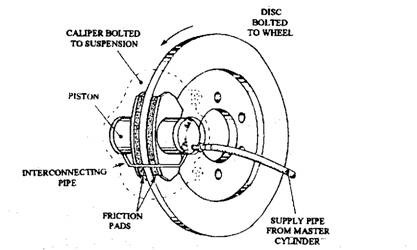
One problem with drum brakes is fade and to minimize this problem the disc brake was developed. It uses an exposed disc that is attached to the hub flange. The two friction pads are pressed on to this disc to provide braking action (Fig. 28.6). The pads are actuated by hydraulic pistons placed in cylinders formed in a caliper, which is secured to a fixed part of the axle.

Fig. 28.5. Cam-operated drum brake.

Fig. 28.6. Disc brake.
The hydraulic pressure forces the friction pads against the rotating cast iron disc. Consequently, the disc motion is retarded and heat generated from the energy of motion is conducted to the disc. Since a large part of the disc is exposed to the air, heat is easily dissipated, so that the brake can be used continuously for long periods before serious fade occurs. In this layout the friction pads move at a right angle to the disc, so that any drop in the friction value does not affect the force applied to the pad. ,
For the application of a disc brake, a greater pedal pressure is necessary to produce a given retardation than that required for a drum brake. Adjustment of pad wear is automatic on a disc brake. In this brake system the pads can also be inspected easily and in the absence of corrosion, the pads can be renewed easily.
