10.29.
Turbocharger
A turbocharger turbine (Fig. 10.61) looks much like the centrifugal pump. Hot exhaust gases from the combustion chamber flow to the turbine wheel, and are heated and expanded as they leave the engine. The expansion of the hot exhaust gases against the turbine wheel’s blades forces the turbine wheel to turn and not the speed or force of the gas.
The main advantage of the turbine over a mechanically driven supercharger is that it does not absorb engine power. In a normally aspirated engine, about half of the heat energy contained in the fuel is lost in the exhaust system (Fig. 10.62). Another 25 percent is used for radiator cooling. Only about 25 percent is actually converted to

Fig. 10.61. A turbine wheel is turned by the expansion of gases against its blades.
mechanical power. A mechanical driven pump uses up a portion of this mechanical output, whereas a turbine receives its energy from the exhaust gases.
The problem of driving a centrifugal blower at very high speeds, and the loss of up to 35 percent of the engine power to provide this drive, can be overcome by using the energy contained in the exhaust gas to supercharge the engine. The combination of centrifugal compressor and exhaust driven turbine is called a turbo-supercharger or turbocharger.
Although in the early years of the last century attempts have been made from time to time to apply this principle to engines, but only during recent years the scheme has been applied to motor vehicles. Since the blades of a turbine have to operate at a high temperature of about 1275 K, it was possible to make an economical turbocharger unit only when a reasonably priced metal became available for the blades.
10.29.1.
Turbocharger Design
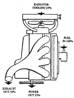
Fig. 10.62. A turbine uses some of the heat energy that normally is wasted.
Normally a radial flow type turbine is used to drive the compressor. It has similar construction to a centrifugal blower, but the direction of gas flow through the unit is reversed (Fig. 10.63). Because of the high temperatures operation the turbine is made of special material, such a nickel or nickel-chromium alloy steel. A cast-iron casing, looked like a snail’s shell, encloses the turbines for the passage of the exhaust gas on to the periphery of the turbine blades. The gas enters through a flange on the casing. The flange connects the unit to the exhaust manifold of the engine. A connection at the centre of the turbine casing forms the outlet passage of exhaust gas to a normal exhaust system.

Fig. 10.63. Radial flow turbine.
A shaft supports the exhaust-driven turbine and transmits the drive to the centrifugal compressor. The casings of aluminium alloy and cast iron are made for compressor and turbine
respectively. These are bolted together to form a single unit which is called a turbocharger (Fig. 10.64).
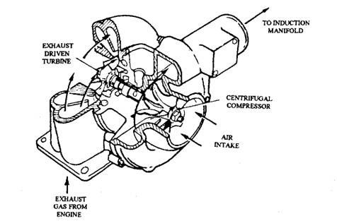
Fig. 10.64. Turbocharger.
During operation of the unit, the exhaust gas at high temperature and velocity from the engine is delivered into the casing. Before the gas flows from the casing to the turbine, it first passes through either specially shaped passages or a ring of guide vanes, so that the gas strikes the outer tips of the turbine blades tangentially to drive the turbine in the required direction. The blades decrease the speed of the gas as it flows towards the centre of the turbine. This action extracts energy from the gas due to which the turbine spins at a high speed of more than 100000 rpm when the temperature and/or velocity of the exhaust gas is high.
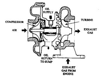
Fig. 10.65. Turbocharger in section.
Due to the high speed of operation, two plain floating bearing (often made of cast iron) are used to support the shaft (Fig. 10.65). These bearings require a pressurized supply of clean oil to resist wear and an adequate flow of oil to keep the bearings cool. Oil is supplied to the bearings through a pipe from the engine’s lubrication system. After passing though the bearings the oil is collected in a cavity, formed in the casing between the compressor and turbine, and then it is allowed to flow naturally back into the engine sump. Special care is taken to ensure that the bearings are not starved of oil when the engine is either started or stopped. The engine should not be accelerated either immediately after it has been started or just pricr to switching off. It takes a long time for the turbine to come to rest.
Oil must not enter the compressor and exhaust gas must not pass to the bearings. To ensure
these oil and gas seals are provided. Oil passing the compressor seal produces a large quantity of blue smoke. Any defect in the turbocharger that malfunctions the action of the seals, such as shaft movement caused by worn bearings, is indicated soon. Poor lubrication, caused by insufficient pressure or dirty oil, is a common cause of rapid bearing wear, which is accelerated when the shaft movement permits hot exhaust gas to escape into the bearings. Onset of these conditions decelerates the life of the unit to a few seconds. Figure 10.63 also illustrates the bearing-and-seal arrangement. This design uses cast-iron sealing rings having a construction similar to a piston ring.
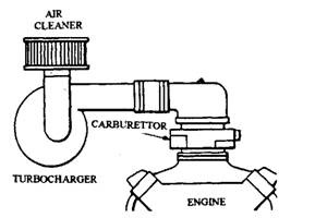
Fig. 10.66. Turbocharger can force air into the carburettor.
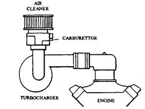
Fig. 10.67. Turbocharger can force the air-fuel mix ture directly into the intake manifold.
10.29.2.
Turbocharger Installation
A turbocharger can be installed either
(i) between the air cleaner and the carburettor (Fig. 10.66) or
(ii) between the carburettor and the engine (Fig. 10.67).
Each of these installations has its disadvantages. When compressed air is forced through the carburettor (Fig. 10.66), the fuel pressure must be sufficiently high so that fuel can enter the airflow. Also the carburettor and all fuel lines must be able to withstand the increased pressure without causing any leak. If air and fuel are mixed and then compressed (Fig. 10.65), the mixture can easily separate. In addition, the car-
burettor must be installed farther away from the engine, which can cause some problems in cold weather.
Diesel truck engines are often turbocharged. With a diesel fuel injection system, the above installation problems do not exit. The turbocharger delivers air to the induction system independently of the fuel injection system. The earliest gasoline engine using both a tur-
bocharger and fuel injection is the German built Porsche Turbo Carrera and the Swedish Saab turbo, which use the Bosch CIS injection system.
10.29.3.
Turbocharger Controls
The operation of a turbocharger must be controlled to avoid high exhaust emissions and detonation. The maximum boost pressure of a turbocharger must also be controlled to save the engine against damage due to the higher compression and power potential. There are three methods of controlling a turbocharger system :
(a) Changing the amount of boost.
(b) Cooling the compressed mixture.
(c) Altering the spark timing.
Each of these methods controls several aspects of a turbochargers operation. The following paragraphs present how the controls are achieved and their effects on turbocharger operation.
Boost Limitation and Control.
The exhaust gas of an SI engine is much hotter than that of a CI engine, so this places extra stress on the turbocharger. Further, to meet the emission regulations relating to the discharge of NOx the boost must be reduced at times when this pollutant is produced. This occurs at high engine speed and/or maximum load. A boost limiting valve (waste gate) is used to meet this requirement, and also to minimize the risk of engine damage. An alternative method of limiting boost pressure is to use a pressure relief (blow off) valve in the induction manifold.
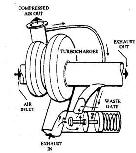
Fig. 10.68. Waste gate.
Boost control systems, therefore, either limits the amount of exhaust gas reaching the turbine, or vents off some of the compressed air or air-fuel mixture before it reaches the combustion chamber.
Waste Gate.
A waste gate (Fig. 10.68) controls the flow of exhaust gas to the turbine. It allows all of the exhaust into the turbine, or routes the exhaust directly to the muffler system. The waste gate action controls maximum boost pressure by limiting the speed of the exhaust turbine. It also controls detonation, to some extent, because the chance of detonation increases with rise of the boost pressure.
Normally waste gates are controlled by a diaphragm linkage. The diaphragm is exposed to intake manifold pressure. When this manifold pressure reaches a certain value, the diaphragm moves sufficiently so that the waste gate routes exhaust gases directly to the muffler and by passes the turbine. Because waste gates are constantly exposed to corrosive exhaust gases, they are made of high-quality alloys.
Blow-off Valve.
A blow off valve, or pressure control valve, varies the flow of compressed air between the turbocharger and the engine (Fig. 10.69). The valve can be operated in different ways depending upon the objective of the control.
When the blow-off valve controls the maximum boost pressure, it works as a simple spring-loaded unit. Once boost pressure reaches a certain value, the spring tension is overcome, and some of the boost pressure is allowed to escape. If the turbocharger is compressing only air (Fig. 10.69) then the air can be vented to the atmosphere. On the other hand, if the turbocharger is compressing the combustible air-fuel mixture, then the mixture is vented back into the turbocharger inlet.
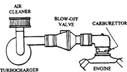
Fig. 10.69. Blow-off valve.
When the blow-off valve controls exhaust emissions, it is operated by intake manifold vacuum. During idle and choked operation, vacuum in the intake manifold causes a diaphragm to move and open the valve. The engine operates as a normally-aspirated unit, avoiding the excessive emissions caused by the turbocharger compression. Some blow-off valves are operated by vacuum routed to one side of the diaphragm and boost pressure routed to the other.
Mixture Cooling.
Two methods are used to cool the compressed mixture before it reaches the combustion chamber. These include intercoolers and water injection systems. The main objective of these systems is to control detonation.
Intercoolers.
Compression of the charge and its passage through a hot turbocharger raise the temperature of the air resulting in a reduction of the density of the charge. To overcome this problem some CI and SI engines use an intercooler between the turbocharger and engine (Fig. 10.70). This unit is generally an air-to-air heat exchanger, which lowers the air temperature to around 325 – 335 K so that the volumetric efficiency is improved and the detonation tolerance is increased.
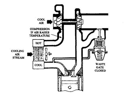
Fig. 10.70. Turbocharger with cooler.
Water Injection. Water injection system cools the compressed mixture by spraying a mist of water, or water and special chemicals, into the intake manifold. This injection is powered either by an electric pump or by boost pressure.
Spark Timing.
Retarding the spark timing controls detonation by lowering the peak temperature of combustion. Spark control system is mechanically or electronically operated.
Mechanical Operation.
A special diaphragm installed at the ignition distributor is exposed to intake manifold pressure. As the boost increases, the diaphragm moves to retard the ignition timing.
Electronic Operation.
A sensor in the engine detects detonation and signals an electric control module. The solid-state circuitry of the module then adjusts ignition timing.
10.29.4.
Turbocharger Failures and Inspection
Turbocharger is generally very dependable. Failures are normally not caused by a component malfunction. Instead, the failure is usually the result of one of these problems. (i) Lack of lubrication. (ii) Contamination of lubrication. (Hi) Ingestion of foreign material.
Turbocharger Inspection Tips.
(i) Remove the air cleaner-to-turbocharger hose and check for any cracks or tears. Inspect the hose for excessive oil. This is usually caused by a restricted crankcase ventilation system or by an overfilled crankcase. A few drops of oil in the hose are normal.
(ii) Inspect the compressor wheel. Pitting or wheel damage is caused by the entrance of foreign material. Rubbing marks between the compressor wheel and housing are caused by excessive bearing clearance or shaft run-out. This can be verified by moving the shaft nut axially. Some movement (about 125 mm) is normal due to bearing oil clearance.
(Hi) Check the rotation of the compressor wheel. The wheel should turn freely with very little drag. Never crank or start the engine unless all turbocharger ducting is in place.
(iv) Remove the exhaust elbow and inspect the turbine wheel. Any damage would be visible on the outer edge of the turbine wheel. Since this is a difficult area to observe, use a small light to look at the wheel blades.
(v) As a general rule, if there is visible turbocharger damage, the entire unit (excluding exhaust elbow) is replaced and not repaired.
(vi) Inspect the turbocharger oil lines for any sludge build up caused by contaminated oil and/or excessive heat. Always flush turbocharger oil liner after a bearing failure in the engine.
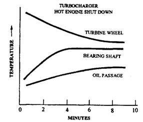
Fig. 10.71. Turbocharger shut down temperature
(vii) Refer to the recommended chart for additional turbocharger trouble shooting information. Make sure that the problem has been corrected before installing a replacement turbocharger.
10.29.5.
Turbocharger Operating and Maintenance Precautions
A turbocharger requires some special operating and maintenance precautions with regard to oil flow and air flow. The turbine wheel operating temperature may approach 1365 K. If a hot turbocharged engine is suddenly turned off, the shaft and passage temperature increases (Fig. 10.71). This may cause oil passage coking and bearing failure. To prevent this (Fig. 10.72), the engine should not be turned off without letting the turbocharger slow down. Let the engine idle a moment before turning the ignition off. Otherwise, engine oil pressure drops while the turbocharger is still spinning at high speed.
Whenever installing a new or repaired turbocharger, the oil feed lines and lubrication channels are primed with as much fresh motor oil as possible. This prevents the turbochargers from running without oil when the engine is first started.
For starting a turbocharged vehicle, always let the oil pressure builds up before reviving the engine. Running the engine at high speeds before the oil pressure builds up results in the turbocharger running with no lubrication. Periodically the condition of total air-flow hoses and clamps are to be checked. Any component that appears after the turbocharger is under pressure must be sealed to prevent pressure loss.
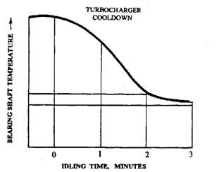
Fig. 10.72. Turbocharger cools down.
