5.2.
The Gas Turbine
5.2.1.
Essential Characteristics
The greater the degree of compression and expansion, and the greater the range of
temperature effectively utilized, the higher is the thermal efficiency and the lower the specific
fuel consumption. These conditions apply to both piston and turbine engines. The three essential
processes in any IC engine are compression of the charge, combustion of the fuel, and expansion
of the products as completely as possible to produce mechanical work. The piston engine can
accomplish the first two processes with high efficiency and reliability. But it is less successful
with the third process due to its incapability of handling large volumes at the low-pressure end
of its expansion. On the other hand a turbine can deal with large volumes at low pressure.
A turbine is a high-speed, unidirectional prime mover capable of handling very large
volumes of fluid flow. It has a high mechanical efficiency (of the order of 85% to 90%) if correctly
designed and manufactured. Its torque increases with a decrease of speed for given input, but
this is accompanied by loss of efficiency since blade angles are fixed. The high rotational speed
of the turbine in comparison to road wheel speeds necessitates the use of a large gear reduction.
A multiple-stages gearing is used to reduce these speeds, and a gas turbine impulse wheel may
be provided with two rows of blades with stationary deflector vanes between them. With this
arrangement, the peripheral blade speed may be about one-third of the initial gas velocity. Even
with this, for automobile applications, a rotational speed of 40,000 ot 50,000 rpm is required to
be provided for in the design. The high rotational inertia consequent on such speeds leads to
troublesome time lag in response to throttle control. However, the advantages with the gas
turbine are the lightness, simplicity and compactness, absence of a cooling system and negligible
oil Consumption.
5.2.2.
Principles of the Gas Turbine
The simple open cycle gas turbine consists of a compressor, combustion chamber, and a
turbine (Fig. 5.14). The compressor takes in ambient air and rasies its pressure. In the
combustion chamber, fuel is injected into the compressed air. The fuel burns in the combustion
chamber raising the temperature and pressure of the working media, which is expanded through
the turbine blades developing mechanical energy. Since ambient air enters at the compressor
and the gases of combustion are rejected to the atmosphere after expansion in the turbine, the
working medium must be continuously replaced. The part of the power developed by the turbine
is utilized to drive engine accessories, as well as the compressor with only the remainder
(approximately one third) available as useful work.
The gas turbine can also operate on a closed cycle in which the working fluid is continuously
recycled through the machine and does not come into physical contact with the combustion
products. Heat is transferred from an external heat source to the working fluid of the cycle by
a heat transfer surface. The closed cycle gas turbine is not discussed in this chapter as
automotive gas turbine engines work on an open cycle.

Fig. 5.14. Simple open-cycle gas turbine.
Compressor
The compressor is the first mechanical element in the turbine cycle. Two types of compres-
sors being used in gas turbines are centrifugal compressors and axial flow compressors. The
most successful rotary compressors produced achieve at best only about 80% of the efficiency of
their piston counterparts, owing to the inherent aerodynamic difficulty of controlling of the flow
of light fluids by high-speed rotary means. The pressure ratios that can be used are also
restricted by the limitations of the compressor. The pressure ratio is defined as the pressure of
the compressed air discharged from the compressor to the pressure of the air entering the
compressor.
Combustion.
The combustor must operate efficiently over a wide range of ambient conditions with widely
varying rates of fuel flow from engine no-load to rated full load conditions. The combustion
chamber must receive the compressed air, the liquid fuel must be injected, and the combustion
be completed before the products are passed to the turbine. This combustion must be carried
out in a light and compact arrangement, capable of withstanding the high temperature of
continuous combustion over an accepted working life. Combustion efficiency is defined as the
ratio of actual heat developed during combustion from a given quantity of fuel, to the total
equivalent heat of the same given quantity of fuel, flowing through the combustion chamber.
Combustion efficiencies of the order of 95 to 98 percent are common in gas turbine engines. Any
loss in combustion efficiency contributes to a direct loss in over-all engine thermal efficiency.
The most common method of injecting liquid fuel is through an atomizer or nozzle assembly as
a fine mist and it is burned in this form. The turbine uses gasoline, kerosene, or oil for fuel. Gas
turbines may use single, double or multiple combustion chambers to handle the combustion
function.
In order to achieve complete combustion, a stoichiometric mixture of approximately 15 parts
of air (by weight) to one part of fuel is required in the primary zone where the combustion occurs.
Since the normal hydrocarbon fuel burns at a temperature around 1925 to 2200 K, the major
part of the air, called secondary air, is utilized to cool the products of combustion down to the
permissible turbine inlet temperature. This provides an overall air-fuel ratio in the range of
50:1 to 250 : 1.
Turbine.
The third element is the expansion turbine, the power-producing element of the engine. The
pressurized hot gases from the combustion chamber provide energy for the turbine. The
temperature of the gases entering the turbine ranges from 970 to 1025 K under continuous full
load operations. The first part of each turbine stage is a nozzle assembly. The nozzles restrict,
accelerate (an expansion process), and direct the flow into the turbine wheel. After passing
through the nozzle and entering the rotor, the hot gas continues its expansion process through
the turbine wheel balding and imparts rotative force to the turbine shaft.
The expansion turbine may be of the axial flow
type or radial flow type. The most widely used type
in low-pressure ratio is a single stage, radial-inflow
turbine in which the gases flow from the wheel rim
radially across the wheel and the exhaust from the
centre of the wheel. For higher-pressure ratios,
either a combination of radial and axial or a two- or
three-stages axial turbine assembly is utilized. The
pressure ratios that can be used are also restricted
indirectly by the inability of the turbine balding and
rotor to withstand for sufficiently long periods the
combination of high temperature and high
centrifugal stresses that are involved in the sub-
sequent expansion process.
If all the turbine stages are on the same shaft as
the compressor, the gas turbine is called a single-
shaft or fixed shaft turbine (Fig. 5.14). The turbine
can be divided into two sections. The portion of the
turbine stages required to drive the compressor,
called compressor turbine, or gas generator
turbine, is put on the same shaft as the compressor.
The turbine stages that supply power to the driven
turbine are put on a separate shaft and are called a
power turbine (Fig. 5.15). This type of turbine is
called a two-shaft or split-shaft or free-turbine
engine.
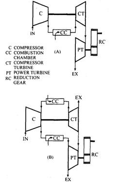
Fig. 5.15. Two-shaft open cycle gas turbine
A. With one combustion chamber.
B. With two combustion chambers.
The basic requirements for the turbines are lightweight, high efficiency, ability to operate
at high temperatures for long periods, reliability, and serviceability. The selection of blade
material depends on the stress-rupture and creep characteristics of the various blade materials,
in combination with mechanical and thermal stresses, resistance to mechanical and thermal
shock, and resistance to corrosion and vibration.
5.2.3.
Gas Turbine Cycle (Ideal and Actual Theoretical)
The gas turbine works on the Joule or Brayton cycle shown in Fig. 5.16 in a temperature-
entropy diagram. The atmospheric air at state 1 enters the compressior and is compressed to
higher-pressure/>2 (with pressure ratio, rp – p<zlp\, where pi is the atmospheric pressure). The
compressed air enters the combustion chamber at state 2 and burns with a hydrocarbon fuel
injected into it. The mixture of products of combustion with secondary air leaves the combustion
chamber and enters at state 3. In the turbine, the mixture is expanded to and exhausted at state
4. The following idealized processes take place for a simple open cycle gas turbine.
(i) Process 1-2. Isentropic or reversible adiabatic compression through the compressor.
{ID Process 2-3. Constant pressure addition of heat (in combustion chamber).
(Hi) Process 3-4. Isentropic or reversible adiabatic expansion through the turbine.
(iv) Process 4-1. Constant pressure rejection of heat to the atmosphere.
This cycle is an ideal cycle, which uses dry air with variable specific heats as the working
fluid following the above processes. The thermal efficiency of the ideal Joule cycle in terms of
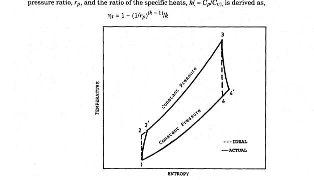
Fig. 5.16. Temperature-entropy diagram of simple open cycle as turbine.
In the ideal cycle, it is assumed that the processes are reversible i.e. isentropic or reversible
adiabatic compression (in compressor) and expansion (in turbine). This implies that the
compressor and turbine efficiencies are 100 percent, which are practically less. The irre-
versibility is caused by the fluid friction losses in the compressor and the turbine. Therefore, in
the actual theoretical cycle (Fig. 5.16), the actual compression and expansion processes depart
from the vertical and are shown at states 2′ and 4′. The cycle 1 – 2′ – 3 – 4′ – 1 is actual
theoretical because it still uses dry air as the working fluid. The compressor and turbine
efficiencies for actual theoretical open gas turbine cycle become,
![]()
The thermal efficiency of an actual simple open cycle gas turbine is heavily dependent upon
the following variables.
(a) Pressure ratio, rp = poJpi
(b) Turbine efficiency
(c) Turbine inlet temperature
id) Compressor efficiency, nc
(e) Compressor inlet temperature (i.e. atmospheric temperature)
Therefore, the possible methods of improving thermal efficiency of the gas turbine include;
(i) increasing turbine inlet temperature
(ii) increasing compressor pressure ratio
(Hi) increasing component efficiencies (i.e. of compressor and turbine)
(iv) use of compressor intercoolers and exhaust gas heat exchangers.
5.2.4.
Exhaust Heat Recovery Devices
In order to increase over-all engine efficiency, a turbine exhaust-to-compressor discharge
heat exchanger can be added to recover some of the exhaust heat and thus reduce the amount
of fuel required to produce a given output power. The heat exchanger can be either of two types;
recuperator or regenerator. In recuperative type, the hot turbine exhaust gas flows on one side
of the heat transfer surface and the cooler compressor discharge air flows in the other side. The
heat passes by conduction from one fluid stream to the other through plate and tubular surfaces.
In regenerative or changeover type, the turbine exhaust heats the intermediate material, for
example a nest of fire bricks, which in turn imparts heat to the compressor discharge air.
Therefore, in this design two streams are directed in turn to frist heat the intermediate material
and subsequently to extract heat from the material. The intermediate material may be of
different types such as layers of screen, stacks of finely corrugated metal or porous ceramic.
Figure 5.17 schematically illustrates a heat recovery cycle.
For light power applications attention is now concentrated on the development of a compact
revolving unit, in which matrices of a suitable material in mesh from are carried in a drum
revolving at 20 to 30 rpm, the two streams passing continuously, each through an appropriate
portion of the rotor profile. Each portion of matrix picks up and transfers heat as it passes from
one stream to the other. The heat recovered in the heat exchanger permits reduction of fuel
input by approximately 25 to 50 percent depending upon the effectiveness of the heat exchanger.
The weight and size of heat exchanger depend directly on the heat exchanger effectiveness.
5.2.5.
Starter System
The function of the starter system is to accelerate the turbine to a speed sufficient enough
for it to be able to start on its own power. Unlike the compression ignition engine, which may
require only a few revolutions of cranking, the gas turbine engine must be cranked to 10 to 20
percent speed before it can sustain itself at all, and to between 30 to 40 percent speed to complete
the start within reasonable time and temperature limits. This is because the compressor and
the turbine components of the engine are designed to operate efficiently at high speed where
their power level is high. Several different types of starting systems are possible, such as electric,
engine, high pressure impingement, hydraulic, hand crank and compressed air or gas. However,
only the electric system is discussed here.
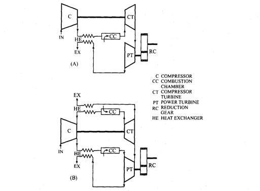
Fig. 5.17. Gas turbine’s exhaust recovery cycle.
Electric. An electric starting system consists of motor, battery changing system, and a
means of connecting and disconnecting the motor and batteries. The high starting torque of a
DC motor qualifies it as a good gas turbine starting means. A DC motor requires a DC power
source to drive it, usually a battery. It is common to use the motor as a generator, after the
engine starts, to charge the battery, and for other purposes. This usage generally requires a
larger motor than if it is used only for starting, since the motor-generator must be rated for
continuous duty while a starter is subjected only to intermittent duty. The motor-generator also
requires a voltage regulating system. Usually, a lead acid battery is used for gas turbine
applications.
5.2.6.
Fuel System
The fuel system consists of piping, manifold, and one or more pumps required for delivering
fuel to the combustor at a sufficient pressure to perform injection satisfactorily. Elements of the
control system such as shut-off valves and regulators are found in fuel systems between the
inlet and combustor.
Gas Fuel System.
The pressure required to inject a gaseous fuel is essentially compressor
discharge pressure plus the presssure losses in the control system and manifolds. A gaseous
fuel injector usually consists of a tube with holes in it. The pressure drop across this injector is
very small.
Liquid Fuel System.
The primary requirement for a liquid fuel system is that it has
sufficient pressure to permit a pressure drop across the injector, which is great enough to
atomize the fuel. The injector is usually a continuously atomizing spray nozzle. The pressure
requirement for atomization varies depending on fuel viscosity and surface tension. Even though
some liquid fuel systems require 3445 to 6900 kPa, the pump power requirements are low. The
fuel pump is often an integral part of the control system.
5.2.7.
Control Systems and Governor
Starting Controls.
The sequence of events required to start, run, and shut down a gas
turbine can be controlled manually but is usually handled automatically. After cranking has
started, and sufficient speed has been reached, the ignition system is energized and fuel is
admitted to the combustor to start combustion. The starter continues to assist the engine,
usually until is attains 30 to 40 percent of full speed, beyond which the engine is capable of
continuing the start under its own power.
Acceleration and Shutdown Controls.
Acceleration after light signal off is controlled by
an acceleration limiter, which schedules fuel to provide an acceleration rate within turbine
design limits. The speed governor assumes control near full speed conditions and provides fuel
corrections as needed to maintain turbine speed under varying load. A shut down signal supplied
either manually or by any one of several protective devices causes the fuel valve to be closed,
thus stopping the engine.
Protective Controls.
The following protective controls are usually supplied with the gas
turbine.
(a) Engine Over-speed. This control provides a means of detecting speeds approaching
safety limits of the engine.
ib) Temperature. Protection for the turbine inlet temperature is provided. Exhaust
temperatures are more easily measured and are directly related to inlet temperatures.
(c) Low Lubrication Oil Pressure.
(d) High Lubrication Oil Temperature.
(e) Flame Detection. Two conditions exist where it is important to know that combustion
is proceeding normally in order to prevent damage to the engine.
In starting, fuel valves are open and ignition is started. If the fuel fails to ignite an explosive
amount of fuel may soon accumulate and cause a hazard. A light off detection method is usually
being provided which shuts off the fuel supply is combustion does not occur within a very short
time after fuel is admitted.
If a loss of combustion occurs during turbine operation, the same hazardous condition may
arise and the fuel supply must be shut off quickly. While the engine looses power immediately,
rotational energy continues to provide fuel pressure for a short period.
(/) Vibration. The vibration may be caused due to an unbalance in the rotating parts of the
turbine or due to unstable combustion.
ig) Fuel Under-pressure. Low fuel pressure either momentary or sporadic could result in
erratic operation and hazardous conditions.
Governor.
The operation of a gas turbine engine generally requires automatic fuel regula-
tion for both starting and normal operation. The governor may perform both functions or a
separate acceleration limiter may be used for starting. Fuel control systems very considerably
depending upon a number of factors, such as degree of automation desired, closeness of speed
regulation, operating characteristics of the particular engine, environmental considerations,
and cost.
5.2.8.
Lubrication System
The function of the lubrication system is to lubricate and cool bearings and gears, whether
the engine uses journal bearings throughout, anti-friction bearings throughout, or a mixture of
the two. Smaller engines, particularly those with anti-friction bearings, use a single engine-
driven lubricating pump, whereas large engines use lubricating pumps driven separately from
the engine. In cold surroundings, an oil pre-start heater is used.
5.2.9.
Turbine Developments
The Rover Company achieved success in 1963 and Le Mans put on race the first turbine-
powered sports car is 1965. The 1963 model did not have an exhaust gas recovery system, and
the fuel consumption was at 2.445 km/1, with an average speed of 173 km/h. In 1964 a
regenerator type heat exchanger was incorporated and a remarkable step in fuel economy was
achieved. At an average speed of 158.3 km/h, the fuel consumption was 1.77 km/1.
General Motors has developed the GT-304 Whirl fire unit using a single-stage centrifugal
air compressor delivering compressed air to a symmetrical pair of revolving-drum type
regenerators where it picks up heat from a hot exhaust stream, before entering the four
symmetrically-placed can type combustors. From the combustors the high-temperature gases
pass through the nozzle ring mounted in a dividing bulkhead to the turbine chamber. The
velocity aquired in the nozzle ring is extracted in the two separate single-stage impulse turbines
located in series. The normal speeds of the compressor and power turbines are 35000 and 28000
rpm respectively, and the regenerators revolve at 20 to 30 rpm.
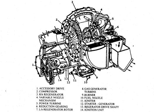
Fig. 5.18. Chrysler gas turbine unit.
Ford Motor Company of America developed a gas turbine engine, known as the 704 models,
which incorporates a novel arrangement in solving the problem of high fuel consumption. The
unit consumes fuel from 0.294 to 0.353 kg/kWh according to load. A two-stage compressor with
inter cooling and compression ratio of 4:1 for each stage is employed. The two stages of
compressor run at 46500 rpm and 91000 rpm. There are two combustion chambers, the first
interposed between the heat exchanger and the high-speed inward flow radial turbine, from
which the gases pass to the secondary combustion chamber where a further supply of fuel is
introduced.
The Chryster gas turbine engine (Fig. 5.18) was developed during 1963 and successfully
installed in a car with limited production. The power plant has two mechanically independent
turbine wheels of the single-stage impulse type, through which the gas stream passes in series.
They are axial flow wheels, the front one driving the single-stage radial compressor with an
extension shaft serving the auxiliaries. Of the two, the rearmost is the power turbine, which is
larger than the compressor wheel, and is provided with variable angle guide vanes. This type
of guide vanes varies the direction of the gas stream according to the load on the turbine.
The regenerator is a symmetrical pair of rotary multi-cellular type and driven by spur
reduction gearing from the compressor shaft at 9 to 22 rpm. A single combustion chamber is
used which is mounted underneath the main casing. The combustion products pass first,
through the fixed guide vanes, to the compressor turbine, and then through the variable angle
guide vanes for the second stages of expansion in the power turbine. The hot exhaust is ducted
to the rear halves of the interchangers where the wheels absorb heat and transfer it to the
contrary air stream from the compressor. The variation of torque and power against output
shaft speed is shown in Fig. 5.19. The power turbine may be stalled to zero speed, but continues
to develop full torque, as the compressor runs independently.
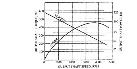
Fig. 5.19. Variation of torque and power vs. speed.
During 1967, Leyland Gas Turbine Ltd. developed a new, large unit producing 260-300 kW
for commercial vehicles. A minimum fuel consumption of0.2373 kg/kWh at 293 K was achieved.
The compressor idling speed is 19000 rpm and the rated power turbine speed is 32500 rpm. The
compression ratio is 4:1. The maximum temperature to the compressor turbine is more than
1273 K. The engine uses a radial-flow impeller and is constructed in two portions. The heat
exchanger comprises of two ceramic discs disposed vertically, one each side of the engine, and
rotated at 1 / 1800 of the speed of the impeller shaft, from which they are driven. The heat
exchanger is of the rotary regenerator type, and a temperature rise of 520 degree over inlet air
takes place.
