9.2.
Tanks and Filters
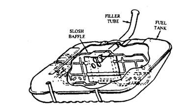
The fuel tank (Fig. 9.3) is made of two halves of corrosion-resistant steel, which are ribbed for additional strength and welded together. Exposed sections of the tank generally made of heavier steel for protection from road damage and corrosion. Some cars and light trucks have an optional fuel tank made of polyethylene plastic. Greater use of plastics in fuel tank construction is likely to become common in the future.
The tank design and capacity depend on the available space, filter location, fuel expansion room, and fuel movement. A filter tube is placed in the tank to avoid complete filling to the tank. The air space created at the top of the tank allows space for fuel expansion. A vertical baffle in the tank controls fuel sloshing during movement of the vehicle. A drain plug installed at the
bottom of the tank is used for emptying the tank. Some tanks also include a fuel filter at their exit and a sump at the bottom, for collection of dirt and water.

Fig. 9.2. Schematic of SI engine fuel system.
Regardless of its size ad shape, a fuel tank must have the following facilities:
(i) An inlet or filter tube, through which fuel can enter the tank, and a filler cap.
(ii) An outlet to the fuel line leading to the fuel pump. (Hi) A vent system.

Fig. 9.3. Fuel tank.
Tank Location and Mounting. Most domestic sedans and coupes generally use a horizontally mounted fuel tank. It is usually suspended below the rear of the floor pan (Fig. 9.4) between the frame rails and behind the rear axle. Many station wagons have a vertically positioned tank, located on one side of the vehicle between the outer and inner rear fender panels. To prevent squeaks, some cars have felt insulator strips cemented on the top or sides of the tank where it touches the under body.

Fig. 9.4. Typical fuel tank installation.
Location of the fuel inlet depends on the design of the tank and placement of the filler tube. It is generally installed behind a filler cap or a hinged door in the centre of the rear panel or in the outer side of either rear fender panel. Fuel tanks are usually secured by a pair of metal retaining straps. The strap ends are bolted to under body brackets or support panels. The free ends are drawn underneath the tank to hold it is place, and then bolted to other support brackets or to a frame member on the opposite side of the tank.
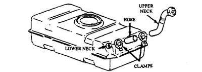
Filler Tubes. Two types of filler pipes are used; a rigid one-piece tube soldered to the tank, and a three-piece unit (Fig. 9.5). The three-piece design uses a lower neck soldered to the tank and an upper neck fastened to the inside of the body sheet metal panel. The two metal necks are connected by a length of hose, clamped at each end.

Fig. 9.5. Three-piece filler tube assembly.
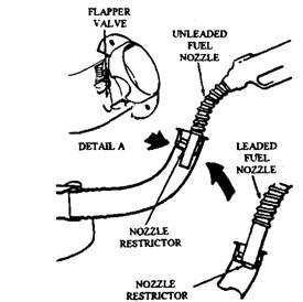
Cars having catalytic converters and also a few models without converters require unleaded fuel for which special filler tube (Fig. 9.6) is incorporated. This filler has a restriction so that the nozzles that can only be inserted are the smaller diameter nozzles of pumps dispensing unleaded fuel. The restrictors may be spring-loaded flapper valves or simple ring-shaped pieces inside the tube.
Tank Venting Requirements.
Fuel tanks are required to be vented to avoid vacuum lock, which prevents fuel delivery. Earlier vehicle models have a direct vent to the atmosphere in the fuel tank by means of a vent line, or through the filler cap. But these arrangements increase air
pollution by allowing fuel vapour into the air. To reduce evaporative hydrocarbon (HC) emissions, controls are added to later models. The fuel tank is provided with a vapour separator, designed to vent the tank under various conditions like when the vehicle is standing in any position, when the vehicle goes up and down hills, as atmospheric pressure changes and as fuel is drawn from the tank. In the emission-controlled vehicles the tank is vented to the atmosphere through a vapour separator and a carbon canister.
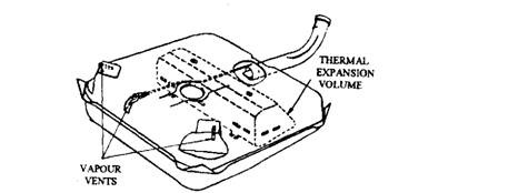
Since fuel tanks are no longer vented directly to the atmosphere, the tank is designed to allow for fuel expansion, contraction, and overflow which result from changes in temperature. One method is to install a separate expansion tank within the main fuel tank, as shown in Fig. 9.7. Another method is to provide a dome in the top of the tank (Fig. 9.4).

Fig. 9.6. Restrictors in the filler tube.

Fig. 9.7. Fuel tank with internal expansion tank.
