15.4.
Starter Motor Construction
A starter motor converts the electrical energy stored in the battery into mechanical energy to crank the engine for starting. A simple electric motor includes a horseshoe-shaped soft-iron yoke with field windings wound around each of the two pole-pieces (Fig. 15.14). The armature winding rotates between the pole-pieces with its ends attached to each half-segment of a split-ring. The current from the positive terminal of the battery flows to the right-hand brush and segment, round the armature loop, and comes out of the left-hand segment and brush. It then circulates through the left-and right-hand yoke field windings and returns to the negative terminal of the battery.

Fig. 15.14. Basic single-loop starter motor.
15.4.1.
Magnetic-torque Production
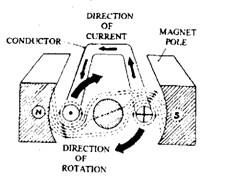
When the current flows through the yoke field windings, it converts the yoke into an electromagnet due to which a magnetic field or flux is created between the pole-pieces (Fig. 15.15). Similarly, due to the flow of current through the armature loop, concentric rings of magnetic flux are established around the two half-conductor cores. This magnetic flux flows anticlockwise around the left-hand conductor and clockwise around the right-hand conductor.
It can be seen from the figure that the magnetic lines of force between the yoke poles and those for the armature conductors travel in the same direction, and the two sets of lines merge and strengthen each other. This is indicated below the left-hand conductor and above the right-hand conductor. Conversely, where the yoke and armature magnetic fields travel in opposite directions, they neutralise each other. Hence, the field strength above the left-hand conductor and below the right-hand conductor is very weak. The difference in the magnetic field strengths above and below each conductor gives rise to a net upward force, exerted on the left-hand conductor and a net downward force, on the right-hand conductor so that a clockwise-rotating torque is applied to the armature loop.

Fig. 15.15. Production of a magnetic torque.

Fig. 15.16. Inertia starter motor.
15.4.2.
Commutation
When battery supplies power to the armature loop, the magnetic-field interaction rotates the loop causing the two half-conductors to change places with each other. Also this alters the direction of the current flowing in the conductor relative to the North and South Poles of the yoke. As a result the loop reverses its direction of rotation and turns backward.
To have the continuous rotation of armature loop in only one direction, the direction of current flowing in each half-loop is required to be reversed every half-revolution, called commutation. This is achieved by connecting the armature-loop ends to a split-ring (Fig. 15.14). As a result each half-ring segment comes in contact with a different brush during every half revolution of the armature, so that the direction of the current flow within the armature loop repeatedly reverses.

Fig. 15.17. Starter-motor commutators and brush-gear.
A. Face commutator brush-gear. B. Axial or face commutator.
C. Radial commutator brush-gear. D. Radial or barrel commutator.
15.4.3.
Starter Specification
The starter motor in practice (Fig. 15.16) uses four field windings and poles, and many armature conductor loops, to produce a more powerful and uniform magnetic torque. Also, to reduce the current flowing in each copper-carbon brush, four evenly spaced brushes are normally used, either of the face type (Fig. 15.17 A and B) or the radial type (Fig. 15.17 C and D).
