16.7.
Spark Plug
The spark plug provides the gap across which the high-tension current jumps to give the spark for ignition of the petrol air mixture. Since the Frenchman Etienne Lenoir invented the spark plug in I860, many significant improvements have taken place there after, but the basic
construction has remained the same, which is consisted of a highly-insulated electrode connected to the HT cable and an earth electrode joined to the plug body.
16.7.1.
Functional Requirements
The spark plug allows a spark to form within the combustion chamber, which initiates burning. While achieving this plug withstands severe conditions. For example a four-cylinder four-stroke engine with a compression ratio of 9 to 1, running at speeds up to 5000 rpm, the following conditions is typical. At this speed the four-stroke cycle is repeated every 24 ms.
• End of induction stroke is at 88 kPa and 338 K.
• Ignition firing point at 883 kPa and 623 K.
• Highest value during power stroke at 4415 kPa and 3273 K.
• Power stroke completed at 392 kPa and 1373 K.
Besides the above, the spark plug must withstand severe vibration and a harsh chemical environment. Also the spark plug’s insulation must with stand voltages upto 40 kV.
16.7.2.
Construction
The construction details of a typical spark plug are shown in Fig. 16.59. A stud connects to the centre electrode to the top terminal. The electrode is made of a nickel based alloy. Silver and platinum are also used for some applications. To improve the thermal conduction properties a copper core is also used in the electrode.
The ‘sillment compressed powder seals’ prevent gas leakage past the insulator. A gasket or tapered seat stops leakage between the cylinder head and the shell. A single-earth electrode of rectangular cross-section is welded to the shell. A hexagon is machined on the shell for easy installation and removal of the plug. Ribs formed on the outside of the insulator increase the length of the flashover or tracking down path outside of the plug insulation and also improve the grip of the lead covers, fitted to prevent penetration of moisture.
The insulating material is high grade ceramic based and aluminium oxide, AI2O3 (95% pure) is a common choice. It is bonded into the metal parts and glazed on the outside surface. The properties of most suitable insulating material are.


Fig. 16.59. Typical spark plug (Bosch).
The above values may be considered as a guide only, as actual values varies with slight manufacturing changes. The electrically conductive glass seal between the electrode and terminal stud is also used as a resistor. This resistor damps the current at the instsant of ignition. Therefore it prevents burn off of the centre^eleetrede, and also it reduces radio interference.
16.7.3,
Plug Terms
The length of the thread, which screw into the cylinder head is called the reach and the diameter of the threaded part indicates the plug size. The common sizes of the plug used are
10, 12, 14 and 18 mm. The latters and numbers stamped on the insulator by the manufacturers provide the following information.
(i) Diameter and reach.
(ii) Seat sealing and radio interference features.
(Hi) Centre electrode features such as the incorporation of a resistor or auxiliary gap.
(iv) Heat range.
(v) Firing end configuration. Figure 16.60 represents the position of the plug in a
cylinder. The seating height ‘A’ is less than the reach to the extent of the thickness of the gasket.
16.7.4.
Heat Range
Due to many constructional features of an engine, the range of temperatures exposed to a spark plug can vary significantly. The operating temperature of the centre electrode is critical. With a too high temperature pre-ignition may occur, because the air-fuel mixture may get ignited due to the incandescence of the plug electrode. On the other hand, with too low temperature of the electrode carbon and oil fouling can occur, as deposits are not fully burnt. Fouling of the plug nose can create shunts (a circuit in parallel with the spark gap). The ideal operating temperature of the plug electrode is between 673 and 1173 K. The variation of temperature of the electrode with engine power outputs is shown in Fig. 16.61.
The heat range of a spark plug is defined as its ability to transfer heat away from the centre electrode. The plugs for a hot running engine should have a higher thermal loading ability than a colder running engine. In this case the hot and cold running of an engine refers to the combustion temperature. The thermal capacity of a spark plug is dependent on the following factors.
(i) The insulator nose length.
(ii) The electrode material. (Hi) The thread contact length. (iv) The projection of the electrode.

Fig. 16.60. Spark plug in cylinder head.
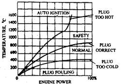
Fig. 16.61. Variation of temperature of the spark plug electrode with engine power output.
All these factors, however, are also dependent on each other. A longer electrode projection reduces fouling problems because of low power operation, stop-go driving and high altitude conditions. To use greater projection of the electrode better thermal conduction is necessary for transferring heat at higher power outputs.
Heat range denotes the temperature range in which a plug operates without causing pre-ignition or lug fouling due to carbon or oil deposits on the insulator. Figure 16.62 provides the heat range and the effect of road speed on the temperature for a typical plug. In addition to pre-ignition and carbon fouling the graph indicates that an operating temperature in excess of about 1023 K causes oxide fouling of the insulator and excessive burning of the electrodes.
The operating temperature of a plug depends on the four factors (Fig. 16.6.3) as follows :
(a Insulator Nose Length. This length from the tip of the electrode to the body forms the heat flow path, which governs the temperature of the insulator nose. If the path is made short, the plug runs relatively cool.
(b) Projection of Insulator. The amount of the projection of the insulator into the combustion chamber governs the amount of cooling obtained from the incoming air-fuel charge. The turbo-action of the charge provides the plug a better resistance to carbon and oxide fouling.
(c) Bore Clearance. The clearance between the insulator and the shell determines the amount of deposit that can be accepted before the plug electrodes are shorted-out.
(d) Material. Rate of heat transfer depends on the thermal conductivity of the materials used, especially in case of the insulator.
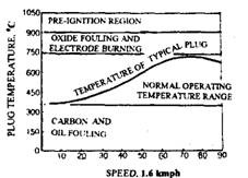
Fig. 16.62. Plug operating temperature.
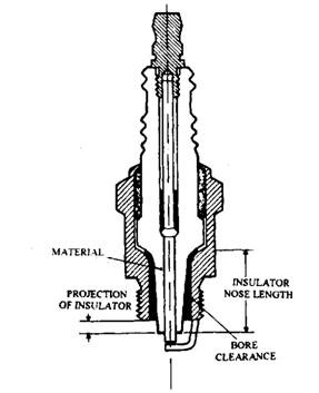
Fig. 16.63. Plug feature affecting temperature.
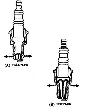
Fig. 16.64. Spark plug heat range.
Two plugs with different heat ranges are presented in Fig. 16.64. The hot (or soft) plug has a long heat transfer path and is suitable for cool running, low-compression engines, and also for engines used continually at low speed for short journeys. If any other type of plug is used on these engines, carbon builds up on the insulator, which causes misfiring after a short period of operation.
At the other end of the heat range is the cold plug, which has good thermal conductivity and is suitable for the engines having a high power output for the size. To summarise as the general rules hot plug is used for a cold engine and cold plug for a hot engine.
16.7.5.
Electrode Features and Materials
Electrode Features.
Generally nickel alloy is used for plug electrodes, which provides resistance to corrosive attack by combustion products or erosion from high-voltage discharges. Platinum is sometimes used in engines where corrosion and erosion are severe. Both electrodes must be strong to withstand vibration from combustion effects. They must also be correctly

Fig. 16.65. Electrode shape.
shaped for the production of a spark with minimum voltage (Fig. 16.65A). Under normal operating conditions, electrodes are eroded and hence after a period of time the earth electrode shape becomes pointed (Fig. 16.65B). In this condition it requires a higher voltage to produce a spark. The increase in the voltage requirement of the plug is accompanied by the deterioration in the output voltage of the ignition generator system. If regularly not attended the system may fail, and most likely this happens during starting of the engine on a cold, damp day.
The material for the spark plug electrode must have
• High thermal conductivity,
• High corrosion resistance, and
• High resistance to burn-off.
For operation under normal conditions, alloy of nickel with chromium, manganese, silicon and magnesium as the alloying constituents are used for the electrode material. These alloys have excellent properties with respect to corrosion and burn-off resistance. To improve on the thermal conductivity, compound electrodes are preferred. This can have a greater nose projection for the same temperature range. A common example of this type of plug is the copper core spark plug.
Silver electrodes are used for specialist applications because this material has very good thermal and electrical properties. Also these plugs can have higher nose length within the same temperature range. The thermal conductivities of some electrode materials are:
• Silver – 407W/mK
• Copper – 384W/mK
• Platinum – 70W/mK
• Nickel – 59W/mK
Compound electrodes have an average thermal conductivity of about 200 W/mK
Platinum tips are used for some spark plug applications as this material has very high burn-off resistance so that much smaller diameter electrodes can be used. This increases mixture accessibility. As platinum has a catalytic effect, it also accelerates the combustion process.
Copper-cored Electrode.
By increasing the insulator nose length the risk of carbon fouling can be reduced when the vehicle is operated on short journeys, but the spark plug seriously overheats if the vehicle is driven at high speeds for long period. To overcome this temperature problem expensive electrode materials such as platinum, iridium, silver or gold-palladium, are used. A cheaper alternative to improve thermal conductivity is a copper-cored electrode (Fig. 16.66).
Electrode Polarity.
When the centerelectrode is negative with respect to the polarity of HT circuit a lower voltage is needed to produce a spark at the plug. A hot surface emits electrons. The centre electrode being the hotter of the two, the natural flow of electrons is from the centre electrode to the earth electrode. If the circuit is connected to allow this direction of flow, then the natural flow of electrons aids, rather than opposing the electron movement provided by the ignition coil. The direction of electron flow in the secondary depends on the polarity of the primary winding. Nowadays the LT terminals on most coils are marked (+) and (-) to indicate the connections required to give a negative spark. Electronic diagnoistic equipment is used to test the coil’s polarity. If this equipment is not available, a pencil test can be carried out (Fig. 16.67). Inspection of a plug, already used for a long time, shows more erosion on the earth electrode when the centre electrode is negative.
16.7.6.
Electrode Gap
For cold starting an engine and for igniting weak mixtures, the duration of the spark is critical. The plug gap must be as large as possible to allow easy access for the mixture to prevent quenching of the flame. Wider gaps are sometimes used for engines, which run on a mixture weaker than normal. These mixtures are more difficult to ignite, so a higher voltage is required.
Spark plug electrode gaps in general increases with the increase of power of the ignition systems driving the spark (leaving aside engine operating conditions). Since, the energy available to form a spark is constant at a fixed engine speed, a higher voltage when used across a larger gap results in a spark of shorter duration. Therefore, a smaller gap allows a longer duration spark. The final selection of the gap is therefore a compromise decided based on testing for a particular application. Plug gaps in the region of 0.7 to 1.0 mm is a common choice at present. A typical spark plug gap is 0.6 mm.
An auxiliary gap (or booster gap) is used on some models. This series gap is formed between the terminal and the end of the electrode. This reduces the build up of carbon on the insulator nose and so improves the plug performance when the engine is operated at low power for a considerable time. The introduction of an extra series gap in the circuit raises the HT voltage and as a result causes the spark to jump the gap rather than short down the carbon on the insulator. To restore normal sparking the plug lead is held, by suitably-insulated tongs, about 6 mm from the plug terminal and the engine is started. After a short time the plug begins to operate normally.
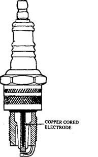
Fig. 16.66. Copper-cored electrode.
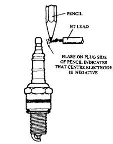
Fig. 16.67. Pencil test to determine polarity.
16.7.7.
*V Grooved Spark Plug
The “V grooved plug developed by NGK reduces electrode quenching and allows the flame front to progress more easily from the spark. To achieve this electrode end is formed into a *V shape so that the spark is formed at the side of the electrode. This provides better propagation of the flame front and less quenching because of the contact with the earth and centre electrodes. Figure 16.68 shows such a plug together with a graph comparing this plug with a conventional plug.
16.7.8.
Selection of Plug
Two methods are generally used for selecting the best spark plug for a particualr application. The temperature range is of prime importance. The first method of assessing plug temperature is the thermocouple spark plug shown in Fig. 16.69. This is an accurate method of temperature measurement but is not suitable for all types of plug.
A second method is based on the technique of ionic current measurement. After initiation of combustion, the conductivity and pattern of current flow across the plug gap are very good indications of the thermal load on the plug. This method permits accurate matching of the spark plug heat range to every engine and provides data on the combustion temperature of a test engine. This technique is also adopted as feedback to engine management systems to assist with accurate control.
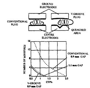
Fig. 16.68. “Vgrooved spark plug firing.
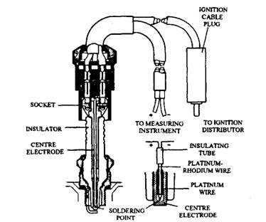
Fig. 16.69. Thermocouple spark plug
