9.18.
Some Commercial Carburettors
9.18.1.
SU Carburettor
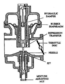
The mixture compensation in this carburettor is achieved by means of a constant vacuum over the jet and varying the effective size of the jet. To provide acceleration a hydraulic damper is incorporated in the piston rod. This causes the effect of slowing down any sudden rise of the piston. When the throttle plate is opened wider, the extra air entering the engine passes through the choke opening, which is temporarily too small at higher velocity. This causes a higher vacuum than normal over the jet, and draws a rich accelerating mixture into the engine. The sectional view of a SU carburettor is shown in Fig. 9.73.

Fig. 9.73. Constant vacuum SU carburettor.
It is utmost important with a SU carburettor to make sure that the mixture strength setting at idle speed is correct. Otherwise any discrepancy in mixture strength at idling speed continues throughout the complete speed range. That means if the idling mixture is set slightly rich, then a slightly rich mixture is delivered at all speeds. The main features of its operation are :
Slow Running. The piston is lifted very slightly from the lower position and the depression caused by the air rushing over the petrol jet provides a small fuel supply to meet the requirements. A separate slow running jet system is unnecessary unless emission restrictions are strict.
Throttle Opening. As the throttle is opened, the mixing chamber depression increases. This allows the piston to rise to a point where the mixing chamber depression is just sufficient to support the piston. The higher the piston moves, the larger is the area of the jet and the greater is the flow of petrol.
Cold Starting. A lever, operated by a cable control, lowers the fuel jet in relation to the needle position. This enlarges the jet opening and increases the amount of fuel for mixing with the air. The initial movement of the control cable slightly opens the throttle to give fast idle action.
Mixture Adjustment. An adjusting nut limits the upward movement of the jet. Unscrewing the nut lowers the jet and enriches the mixture throughout the entire speed and load range of the engine and visa versa.
Hydraulic Damper. This restricts the rate of upward movement of the piston during acceleration providing a slight enrichment of the mixture. The damper also reduces piston flutter caused by the irregular flow of air through induction systems.
Over-run Limiting Valve. This is a spring-loaded valve mounted in the throttle butterfly. When the engine over-runs (i.e. road wheels drive the engine) with the throttle closed, the valve opens and supplies a fuel mixture to reduce the exhaust pollution.
9.18.2.
Zenith Carburettor
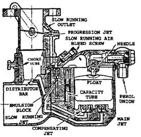
A Zenith V-type carburettor is shown in sectional view in Fig. 9.74. The mixture compensation in this case in achieved by incorporating a gravity jet as well as simple jet in the same carburettor. Thus the weakening characteristic of the former is balanced by the enriching characteristic of the latter providing constant mixture strength over the speed range.
To obtain a rich mixture for starting a strangler valve, fitted on the air inlet side of the emulsion beak, is closed. As a result, only a small amount of air can enter the engine and this, in combination with fuel drawn from the main system, produces a rich mixture.

Fig. 9.74. Zenith V-type carburettor.
9.18.3.
Zenith-Stromberg Constant-depression (CD) Carburettor
Figure 9.75 shows the construction of this type carburettor is sectional view. Whereas the SU type uses a piston, this carburettor has a synthetic rubber diaphragm.
9.18.4.
Solex Carburettor
The mixture compensation in this carburettor is attained by the “air-bleed” principle. Figure 9.76 presents the sectional view of the solex “Assembly 20″ carburettor’s starter, main and idling systems. This type of carburettor gives excellent mixture correction and distribution.
For supplying rich starting mixture, the butterfly throttle valve is closed and petrol and air in predetermined proportions are provided to the engine through the outlet below the throttle. This mixture is supplied by a separate starting carburettor, instead on the side of the main carburettor, which shares the same float chamber.

Fig. 9.75. Zenith-Stromberg carburettor.

Fig. 9.76. Solex “Assembly 20″carburettor.
9.18.5.
Ford Variable-venturi (W) Carburettor
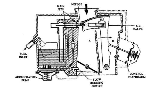
This carburettor has many interesting features, which help to reduce harmful exhaust emissions. It also overcomes the two main disadvantages of the fixed-venturi carburettor, i.e. the need for mixture correction devices and the choke air speed problem, which causes poor atomisation of fuel at low speeds and breathing restriction at high Speeds. Figure 9.77 represents a diagram of this type of carburettor. An air valve, operated by a diaphragm, is used to vary the area of a large, fixed venturi. A tapered needle, attached to the air valve, fits into a main jet to control the petrol flow.

Fig. 9.77. Ford variable-venturi carburettor.
Air Valve Operation. The operating principle of this valve is similar to other variable-venturi carburettors. In Fig. 9.77, the carburettor is shown in the cruising position. A depression in the mixing chamber (A) is communicated through the air valve chamber (B) to the diaphragm chamber (C). Under steady operating conditions of the engine, the difference in air pressure on the diaphragm balances the force provided by the diaphragm spring.
When the throttle is opened a given amount, the following events take place in quick succession:
(i) Depression becomes more intense in the mixing chamber (A) because insufficient air passes through the air valve. This depression is transferred to the diaphragm chamber (C).
(ii) Atmospheric pressure now pushes the diaphragm against the spring. As the diaphragm deflects, the linkage moves the air valve and increases the venturi opening. This prevents the increase in the venturi air speed and restores the depression in the mixing chamber (A) to the original value. At this point the various forces on the diaphragm are balanced.
When the throttle opening is reduced, a ‘reverse’ action is produced, in that the depression in regions (A) and (C) diminishes and consequently the spring closes the air valve preventing a decrease in the venturi air speed. Through this operation, the air valve maintains the venturi air speed constant irrespective of throttle opening.
Slow Running. To meet the stringent conditions of emission control, the modern carburettor must provide a better atomised and distributed slow-running mixture. This is achieved in the W carburettor by incorporating a separate slow-running system. This system is similar to that used in modern constant-choke units except that in the W design the slow-running system supplies about 70 percent of the total mixture and the remainder is provided by the main jet.
Acceleration. A slightly rich, well-atomised mixture is obtained through a vacuum-operated accelerator pump. The mixture strength provided by this pump compensates for the sudden drop in venturi air speed caused by the rapid opening of the air valve.
Cold Starting. When the engine is cold, an automatic choke in the form of a miniature auxiliary carburettor supplements the mixture being provided by the main system. Automatic control is obtained by a bimetallic spring, heated by the engine coolant. The heat-sensitive bimetal spring acts on a needle in the fuel jet, which opens when the engine is cold. Fuel from this jet is mixed with air and the resultant mixture flows into the main system at a point beneath the throttle valve.
