25.5.
Sliding-mesh Gearbox
25.5.1.
Four-speed and Reverse Double-stage
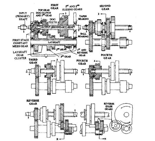
A sliding-mesh gearbox (Fig. 25.11) is similar to a constant-mesh gearbox, but differs in the way the individual gears are engaged. In the sliding-mesh gearbox, the individual gear ratio is chosen by sliding the selected gearwheel axially along the splined main output shaft until it meshes fully with the corresponding layshaft gear cluster. The sliding main shaft gearwheels and their corresponding lay-shaft gearwheel clusters have to be of the spur straight-tooth form, so that when engaged there is no side thrust unlike helical-cut teeth. The major problem with this type of gear engagement is that, while attempting a gear change, the speeds of the input and output shafts are matched first, otherwise the sliding teeth of the mashing gearwheels does not align and hence crashes into each other.
Transmission shafts and gears are generally manufactured using low-alloy nickel-chromium-molybdenum steels. This type of gearbox is presently used only in certain commercial vehicles where a large number of close gear ratios are required in a compact form.
The engine shaft (clutch shaft) contains the main drive gear A, which rotates at the speed of the clutch shaft. The main drive gear is in constant-mesh with counter shaft (lay shaft) drive gear B. Since all the gears on the lay shaft are rigidly fixed, they also rotate along with the clutch shaft. The main shaft is held in line with the clutch shaft. All the gears on main shaft can be slid back and forth on the main shaft spines using shifting forks. The different gear ratios of sliding-mesh transmission may be obtained as follows. N and T with proper suffixes denote the rpm and number of teeth respectively.
First or Low Gear Ratio, G1
The position of gears to obtain this ratio is shown in Fig. 25.11. Transmission of power takes place from the engine shaft (clutch shaft) to lay shaft through gears A and B and finally it is transferred from lay shaft to main shaft (driven shaft) through gears C and D. Hence,
![]()
Second Gear Ratio, G2
Figure 25.11 shows the second gear in action. Power from A goes toB and from there it goes to E, which is on the same shaft, i.e. lay shaft. From E it goes to F, on the main shaft.
![]()
Third Gear Ratio, G3
When the third gear is in action as shown in Fig. 25.11, the drive is from the engine shaft to lay shaft through the constant-mesh gear A and B and finally from lay-shaft to main shaft through gears G and H.


Fig. 25.11. Four-speed-and-reverse double-stage sliding-mesh gearbox.
Fourth or Top Gear Ratio, G4
The drive is direct from the engine shaft to main shaft by engaging gears, A and H with the help of dog teeth provided on them. The whole arrangement is shown in Fig. 25.11. The lay-shaft in this case revolves idly. The gear ratio is 1 to i.e. g4 = 1.
In all the above cases, the direction of rotation of engine shaft and main shaft is the same. The lay shaft rotates in opposite direction.
Reverse Gear, Gr
The reverse gear works as shown in Fig. 25.11. The idler is compound type having two wheels 7l and I2 of different diameters mounted on a shaft, which is parallel to the main shaft. The idler is slid so that H engages pinion C and I\ comes in mesh with the gear D. The reverse drive takes place through A to B, then C to H and finally from ii to D.

