30.2.
Signalling Equipment
30.2.1.
Horns
As per the regulation, a motor vehicle must use an audible warning device (horn) capable of emitting a continuous note which is not too loud or hash in sound. The note produced by the horn should not be a noise, rather musical to avoid annoyance to the public. To provide a pleasing and penetrating note, two horns are often used. One of them emits a high pitch note capable of overcoming traffic noise and the other a low pitch, to carry over a distance. The pitch of a note is its frequency, which is defined as the number of oscillations made per second. The unit of frequency is the hertz (Hz) which is one oscillation per second.
All most all the horns are operated electrically where the note is produced either by magnetically vibrating a diaphragm or by pumping air past a diaphragm into a trumpet. Three types of electric horn in use are high frequency, wind tone, and air horn.
High Frequency Horn (HF).
This type of horn is comparatively cheap and is in use for many years. An electro-mechanical action causes a steel diaphragm to vibrate at about 300 Hz, which oscillates a tone disc at about 2000 Hz. The combined sound produces a highly penetrating note required for a normal horn.
Figure 30.14 illustrates how the action of a magnetic field winding on an iron core produces an oscillatory movement of the diaphragm. Once the horn button is pressed, the circuit closes causing flow of the current of about 4 A around the field coil. This produces a magnetic flux, which attracts the armature. The contacts are opened once the armature has moved a preset distance. This causes the magnetic field to collapse due to which the natural spring of the diaphragm returns the armature and closes the contacts. This cycle of operation continues till the horn button is pressed.
Windtone Horns.
This horn also uses an electrical operating system similar to the high frequency horn for moving the diaphragm. However in this system instead of oscillating tone disc, a windtone horn vibrates, or resonates, a column of air enclosed in a trumpet (Fig. 30.15). The

Fig. 30.14. High frequency horn and circuit.
sound is produced in the trumpet in similar way to a wind instrument. The pitch of the note depends on the length of trumpet and in practice a fairly trumpet is necessary. To accommodate this length it is often shaped in a spiral from, or like a snail’s shell.
Normally two horns are fitted to a vehicle, which are harmonically tuned to the interval of a major third. Horns should be mounted flexibly to minimize the transmission of external shocks, which affect the quality of the horn note. Generally the horns, especially the windtone types, consume a total current in excess of 10 A, and therefore to prolong the life of the horn switch a relay is normally incorporated (Fig. 30.16).
Air Horns.
An air horn uses a trumpet and air is forced through it by means of an electrically driven air nump. A diaphragm valve fitted at the end of the trumpet indicates vibration of the air column in the trumpet. When the horn switch is pressed, the air-compressor discharges air into the pressure chamber in the horn. The air pressure deflects the centre of the diaphragm due to which some air escapes into the trumpet. Consequently the slight pressure drop in the chamber closes the diaphragm valve and the cycle thus repeats. The rate of vibration of the diaphragm and the trumpet length control the pitch and quality of the note emitted.

Fig. 30.15. Widstone horn.

Fig. 30.16. Horn circuit with relay.
Horn Faults and Maintenance.
Since horns are often positioned in an exposed place behind the radiator grill, special care is required to avoid the entrance of moisture. Most faults occur in the horn system due to cable and connector problems. Therefore, when a fault is present-a visual check must be made, which should be followed by a voltmeter test to ensure the application of correct voltage to the horn. When used for a long period, the horn contacts may need resetting for which an adjusting screw is provided. The position of the screw is varied until the horn consumes the specified current. A HF horn typically uses 4 A.
30.2.2.
Directional Indicators and Hazard Warning Systems
For pre-warning signal to the other road users, the amber-coloured lights are flashed to indicate that the driver intends to turn or overtake. As per the regulation, vehicles manufactured after 1986 must incorporate three indicating lamps on each side that flash simultaneously at the rate of 60 – 120 flashes per minutes. In addition, a tell-tale indicator for the driver must be fitted. These lights must be visible through a given angle, and each unit must have the appropriate ‘E’ marking for its position and the bulb must be rated at 15 – 36 W.
The layout of a typical directional indicator circuit is shown in Fig. 30.17. When the switch is turned to the left or right, current is made available to the appropriate lamps. Regular interruption of the current to provide a flashing light is carried out by the flasher unit, which is located on the battery side of the switch.
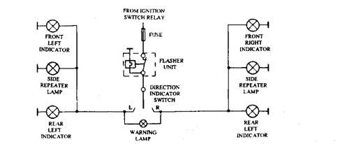
Fig. 30.17. Directional indicator circuit.
When the vehicle breaks-down on the highway, the driver should be able to warn other drivers by flashing simultaneously all the directional indicator lamps. This hazard warning feature is activated by a separate switch operated by the driver (Fig. 30.18). The three common types of flashing system in use are thermal, capacitor, and electronic.
Thermal Type Flasher.
The heating effect of an electric current to bend or extend a metal strip is used in this type of flasher. One design incorporates two bi-metallic strips where each strip is wound with a heating coil and fitted with a contact. When current passes through the coil, the strips bend, opens and closes the contacts.
Another design of thermal flasher is the vane type which is a compact, reliable and cheap unit (Fig. 30.19). It uses a rectangular, snap-action, spring-steel vane, supported at a point midway along the longer side. A thin metal ribbon is diagonally connected to the corners of the
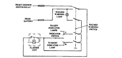
Fig. 30.18. Hazard warning circuit.
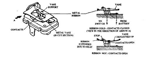
Fig. 30.19. Vane type flasher. vane, and pulls the vane towards the base.
The electrical circuit is made by a pair of contacts, one located on the centre of the ribbon and the other fixed to the base. The flasher unit is installed in series with the lamps so that current to these lamps passes though the metal ribbon, vane and contacts.
Operation of the switch is instantly indicated by the signal lamps. The heating effect of this current increases the length of the metal ribbon, which allows the vane to click upwards to its natural position. Consequently the contacts are opened, which breaks the circuit and extinguishes the signal lights. After a short time the ribbon cools down and contracts as heating is discontinued. This clicks the vane downwards and once again closes the contacts to repeat the cycle of events. Since the time taken to heat the vane depends on the current, the flash frequency is governed by the lamp load. Failure of one of the lamps reduces the electrical load, which causes the vane to be inoperative due to which the remaining lamps glow continuously.
Capacitor Type Flasher.
These designs use the timer action of a capacitor during performing its charging-discharging cycle to trigger a relay which is turn controls the switching and flashing of the signal lamps.
Electronic Type Flasher.
Electronic flasher units are more efficient than the thermal flasher units. This type provides both audible and visual warning signals when a bulb has failed, thereby meets international standards. Failure of the bulb is indicated by the lamps flashing at twice the normal rate or by using an extra warning lamp. The electronic type flasher exhibited in Fig. 13.20 can provide a direction indicator signal load of up to 98 W without altering the flash frequency in addition to a hazard warning signal for many hours of continuous use.
The system normally incorporates in electromagnetic relay to control the current to the signal lamps. The relay method of switching provides an audible signal as well as it is not affected by the high voltage spikes produced during the switching opera’ion. In addition, the relay contacts have very little voltage drop. The drop across the relay contacts is about one-tenth of that of a transistor. Even through transistor switching is ideal for high speed applications, the relay is still preferred for slow-speed, heavy-current switching action.
The basic system of a typical flasher unit uses a printed circuit board, which contains an I.C., capacitor, relay and three resistors (Fig. 30.21). The I.C. chip has three main sections ; an oscillator, relay driver and lamp failure detector. A Zener diode installed in the I.C. controls the operating voltage of the chip and ensures constant flash frequency over a supply voltage range of 10 – 15 V.
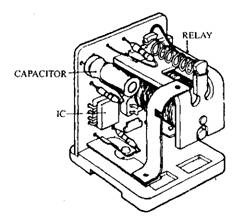
Fig. 30.20. Electronic flasher unit (Lucas FL 19).
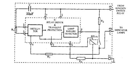
Fig. 30.21. Typical electronic flasher circuit.
The charge-discharge action of the capacitor C provides the timer control for the oscillator. This operates in conjunction with the resistor Ri and provides a R-C time constant for a flash frequency of 90 per minute with a 50-50 off-on signal time. Pulses from the oscillator are passed to a Darlington amplifier relay driver, which provides the current pulses to energize the relay coil. Transient protection of the output transistor is achieved through a diode across the collector-emitter of the power transistor. This causes the self-induced charges in the relay coil to bypass the transistor.
The lamp-failure detector senses the voltage drop across the resistor i?2. This resistor in turn senses the current passing to the signal lamps through the relay contacts. When a lamp fails, the lower current flow decreases the voltage drop (IR drop) across the resistor. This reduced voltage causes the detector to alter the resistance of the R-C time element due to which the frequency of flashing is doubled.
30.2.3.
Maintenance
The common faults encountered are bulb failure and loss of earth at the lamp. These faults are detected by observing the rate of flashing, but this rate may be slower or faster depending upon the type of the flasher. Earth problems are often due to a bad connection of the earth cable, which can normally by noticed by a visual check.
If a system that does not flash with the bulbs alright then it is due to an open-circuit in the supply line, which can be detected by a voltmeter. If a flasher unit fails to operate when full voltage is applied, then it is considered as faulty only when a substitute unit fitted in the circuit confirms that the remainder of the circuit is serviceable.
