22.15.
Roll Axis and the Vehicle under the Action of Side Forces
The vehicle tilts or rolls about an axis lying in the vertical plane containing the centre line of the vehicle due to the action of side forces on it. This axis is called the roll axis whose position depends upon the type of suspension used for both rear and front of the vehicle.
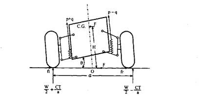
Figure 22.72 shows the vehicle with conventional suspension viewing from the back. The suspension spring (leaf spring) has been shown by zigzag lines.


Fig. 22.72. Vehicle with conventional suspension (viewed from back).
When no side force is acting, reaction at each wheel = W/2 and the load carried by spring = W/2.
When the side forces act on the vehicle it sets up forces ft and ft at the positions of contact of the body with the spring. It is assumed that ft = ft and their resultant (= F) passes through O. Thus side force constitutes a couple T ( = Fh) due to which the left spring is compressed and the right spring is expanded causing a tilt 8 of the vehicle through the point O. Now as shown in Fig. 22.72, the wheel load and the spring load change to (W/2) + (C 77a) and (W/2) – (C Tla) for the left side and right side respectively, where C is constant whose value depends upon the relative stiffness of the springs at the front and the rear, and equal to half when these stiffnesses are assumed equal. The weight of the body through CG is displaced sideways due to the tilt so that a couple is constituted, which introduces an additional moment thereby increasing the tilt, however this is quite small.
![]()
Tilt can be made smaller if the spring base is kept large.
Now the vehicle with independent suspension system of double-arm parallel type is considered under the action of side force F as shown in Fig. 22.73. In this case, as before the side force causes a couple T (= FH) due to which the vehicle tilts about the point O as centre lying on the ground. The wheel loads change to (W/2) + (C Tla) and (W/2) – (C Tla) while the spring loads change top + q andp – q.
![]()

Fig. 22.73. Independent suspension system (double arm parallel type) underaction of side force.
Since a is greater than d, the tilt with independent suspension is less than that in the conventional type of the same couple C. But if we consider equal magnitude of side force, then the couple is greater in the case of independent suspension than in the other as H is greater than h, which increases the tilt in the former case. However, the effect of greater effective spring base (a > d) out-weights the effect of the increase in the arm (H > h) giving 8 less in most cases for independent suspension systems.
Similar to the point O on the rear side, there is a point on the front side. The line passing through these two points is called the roll axis of the vehicle. The roll axis for a car, having both rear and front conventional suspensions, lies a little higher than that having independent suspension at the front and rear.
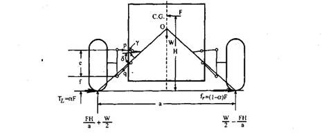
The analysis of an independent suspension under the action of a side force is different from the one under the action of a pure couple as discussed above. Let us consider an independent suspension system as shown in Fig. 22.74 under the action of side force F, then
![]()

Fig. 22.74. An independent suspension system under action of side force.
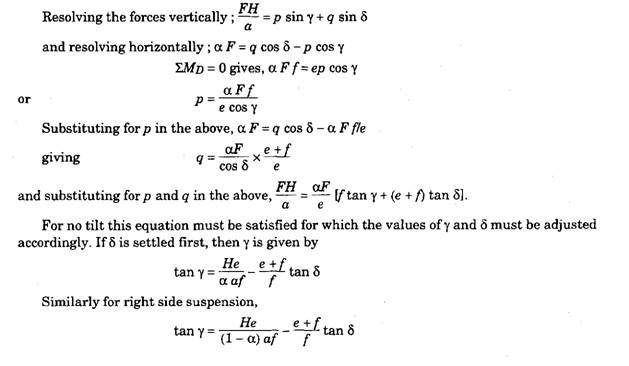
Under the action of the side force the body tilts about the roll axis 0. The wheel reaction becomes, (W/2) + (FH/a) and (W/2) – (FH/a) and the spring load changes correspondingly. If the condition of no tilt is achieved due to proper disposition of links then changes in the spring forces must be zero. Therefore, the changes in the wheel reactions, FH/a must balance the changes in the forces in the links of suspension. Let these forces in the links be p and q and the inclination of links to the horizontal are respectively y and 5 as shown in the figure. Let the left side suspension be considered first.


