15.6.
Pre-engaged Starter Motor
The pre-engaged starter motor is employed for high-compression engines with automatic transmission system such as large petrol engines and small diesel engines. When the ignition is switched on and the starter switch is closed, current from the battery flows to the solenoid windings (Fig. 15.19) generating a magnetic field. The plunger is then drawn towards the windings causing a tilt to the fork lever on its pivot. The pinion, mounted over the helical splined portion of the armature shaft, moves forward and twists relative to the shaft causing an easy mesh with the ring gear. When the pinion is fully engaged, the solenoid contacts are closed, so that current flows from the battery to energise the starter field and armature windings. The armature shaft then rotates and cranks the engine.

Fig. 15.19. Pre-engaged starter motor.
Once the engine has started, the ignition startei switch is released causing the flow of current to ceas< through the solenoid windings, so that the plungei returns by spring tension to its original position. This opens the solenoid contacts and withdraws the pinior from the flywheel teeth. However, if the pinior remains in the engaged position after the engine has started, the free wheel roller clutch automaticallj disengages the pinion inner member from the outei member attached to the armature shaft so that tht armature is prevented for rotating at an excessivel) high speed.
The starter solenoid switch enables a relativelj small current to control a very large current of the order of several hundred amperes, and reduces the voltage drop in the starter circuit due to the use of much shorter cables.
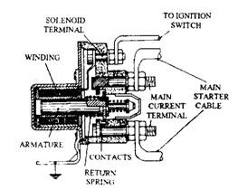
The solenoid switch uses an electromagnet with one end of its winding earthed to its casing and the other end fixed to a small terminal (Fig. 15.20). When the ignition starter switch is operated on, a small current energises a solenoid plunger and a moving contact. This bridges the gap between two fixed heavy current contacts so that current from the battery flows directl} to the starter motor through the contacts. Figures 15.21 and 15.22 illustrate the complete wiring circuits for inertia and pre-engaged starter-motors respectively.

Fig. 15.20. Starter solenoid switch.

Fig. 15.22. Pre-engaged-starter circuit.
