27.8.
Power Assisted Steering
27.8.1.
Need for Power Assisted Steering
A reduction in input effort on the steering wheel rim in a manual steering system is possible by decreasing the steering box gear ratio. This increases the number of steering wheel turns from lock to lock due to which manoeuvring of the steering takes longer, and accordingly the vehicle’s safe cornering speed has to be reduced. Due to the requirement of more weight on the front steering wheels of front wheel drive cars and the use of radial ply tyres with greater tyre width, larger static turning torques are necessary. Therefore, for faster driving and cornering, power assisted steering is desirable and in some cases essential if the vehicle is to be handled to match its performance.
Incorporation of power assisted steering on passenger cars reduces the drivers input to about 25 – 30% of the total effort needed otherwise to manoeuvre it. In heavy trucks the hydraulic power (servo) assistance can be in the order of 80 – 85% of the total steering. As a result, a more direct steering box gear reduction can be used to provide a more precise steering response. Consequently, the steering wheel movement from lock to lock can be reduced approximately from 3.5 to 4 turns for manual system to about 2.5 to 3 turns for power assisted steering arrangements.
The amount of power assistance provided to the steering linkage is normally restricted due to which the driver experiences the tyres interaction with the ground under the varying driving
conditions (Fig. 27.62). Consequently sufficient resistance is still transmitted back to the steering wheel from the road wheels so that the driver can sense the steering input requirements needed to steer the vehicle effectively.
Figure 27.63 illustrates the effects of reducing the input effort at the steering wheel with different steering gear overall ratios to overcome an output opposing resistance at the steering box drop arm. A typical power assisted steering input effort curve operating over a similar working load output range is also plotted with these manual steering gear ratios. From these plots it can be seen that for very low road wheel resistance roughly up to 1000 N at

Fig. 27.63. Comparison of manual steering with power assisted steering.

Fig. 27.64. Power assisted steering layout (control flow system).
the drop arm, the input effort of 10 to 20 N is practically all manual. This initial manual effort at the steering wheel enables the driver to feel the changes in resistance to steering under different road surface conditions, such as a slippery road.
The power assistance arrangements should satisfy certain requirements. It must be ‘failsafe’, that means if the power system fails the driver must still be able to retain effective control. The amount of power assistance should be proportional to the effort put by the driver and the driver must be able to retain the ‘feel’ of the wheels. Hydraulic power is used on light vehicles to assist the driver to steer the vehicle.
27.8.2.
Hydraulic System
Hydraulically operated power assisted systems work on either a constant pressure or constant flow layout. The former incorporates a hydraulic accumulator to store the pressure. The latter uses flow of fluid around the system continuously until assistance is required.
The Components.
The essential components required to operate a constant flow system are shown in Fig. 27.64. The system incorporates a pump, control valve and ram cylinder in addition to the normal steering components.
Pump.
An eccentric rotor pump driven by a vee belt from the engine crankshaft is normally used. The pump is located either on the front of the engine or at the front of the crankshaft. A fluid reservoir is attached to the pump and generally stores a low-viscosity mineral oil similar to the type used in an automatic transmission. A pressure relief valve limits the maximum
pressure of 7 MN/m2, and once this pressure is attained the oil passes from the pump outlet back to the reservoir.
Control Valve or Reaction Valve.
In the layout shown in Fig. 27.64, the valve is located between the two halves of the drag link. It can also be positioned together with the ram cylinder in the steering box. A spool type valve is attached to one half of the drag link and is held centrally in the valve body by two reaction springs. Flexible pipes are used to connect the valve to the ram cylinder, pump and reservoir.
Ram Cylinder.
A double acting ram piston is connected to the steering arm to provide appropriate force in either direction to assist the drive. One side of the cylinder is vented and the other side is pressurized for the force to act in either direction. Assistance given by the ram depends on the fluid pressure available to it by the control valve.
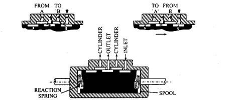
Fig. 27.65. Control valve principle.
The pressure surface in most power steering systems is located in the steering gear, called integral type. Also in some power steering systems it is located in an exterior power cylinder connected between the steering linkages and vehicle frame, called link type. This is similar to a power rack and pinion arrangement.
Operation.
Operation of the system depends on the driver’s input torque applied to the steering wheel. Under low torque conditions, represented in Fig. 27.65, no assistance is required. Application of low torque on the wheel is insufficient to overcome the tension of the reaction springs in the control valve, so that fluid flows back to the reservoir. In this phase of operation, the control valve remains in the neutral position and hence offers no resistance to the oil flow to or from the ram cylinder.
The torque applied by the driver is controlled by the strength of the reaction springs. When this torque reaches a predetermined value, the greater force acting in the drag link operates the valve. The valve connects one side of the ram to the pump and the other side vents to the reservoir. Interruption of the fluid circuit in this manner allows the pump pressure to build up quickly. Consequently, the thrust on the ram also builds up until the movement of the ram overcomes the resistance of the road wheel. At this stage the force in the drag link reduces, so that the valve returns to the neutral position and the system pressure drops to the original value. Thus in this sequence of operation, steering wheel torque opens the valve and the ram exerts a proportional thrust to close the valve.
Turning the steering wheel in the opposite direction also produces a similar action, but in this case the movement of the control valve directs fluid to the other side of the ram piston. There are different designs of reaction valve and spring. One from incorporates a small torsion
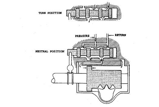
Fig. 27.66. Operation of a power steering control valve.
bar to transmit the drive between the inner column and the gear in the box. When the torque exceeds a given amount the bar twists to move a valve, which activates the ram.
27.8.3.
Control Valve Principle
Types and Operation
During operation of the engine, the fluid in power steering keeps flowing from the pump to the control valve, then back to the reservoir and both the pressure surfaces are exposed to the same system pressure. In the straight ahead position of the wheel, the fluid flows through the circuit. With the increase of steering effort, the valve shift also increases exerting proportional amount of pressure by directing fluid to one pressure surface and increasing the size of the return passage opening from the opposite pressure surface to the reservoir. Figure 27.66 illustrates the principle of operation of the control valve in neutral and during a turn. The control valve is either located inside or is attached to the exterior of the integral type power steering gear. In the link type power steering gear, the valve may be built into the end of the power cylinder or be a separate unit.
The mechanical input force applied by the steering wheel on one hand and the mechanical-hydraulic resistive force of the steering linkage and tyres on the road on the other hand keeps the control valve balanced. As the steering wheel is turned, its mechanical input force moves the control valve towards the linkage resistive force. In this position, the control valve restricts the pressure area and outlet flow to cause pressure builds-up on the pressure surface in a direction that assists the steering wheel input force to move against the steering linkage resistance. Once the steering wheel reaches the desired position, it is held steady and the linkage finally cataches up, centering the control valve to terminate assist. When no effort is being applied to the system, the centering springs centre the spool position to balance pressure on both pressure surfaces, holding the steering linkage in place. With steering wheels in position, if the front tyres hit an object that tries to deflect them, the control valve adds pressure on the

Fig. 27.67. A sliding spool control valve in sectional view.
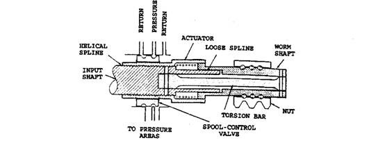
Fig. 27.68. A torsion bar actuated sliding control valve in sectional view.
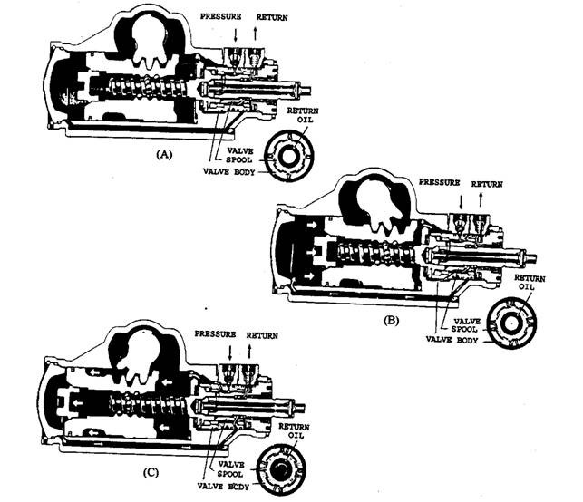
Fig. 27.69. A torsion bar actuated rotating control valve.
pressure surface that opposes the upsetting force, allowing the driver to maintain vehicle control.
The control valves may be of sliding spools or rotating spools type. The control action is same for both the types of valve. In the link type units the sliding spool valve is mounted concentric with the worm shaft between the Pitman arm and steering linkage, and in integral type it is placed parallel in housing outside the steering gear case. The rotary spool type valve is always mounted concentric with worm shaft. The actuation of the sliding spool valve in the integral steering gear is carried out by a slight endwise movement of the worm shaft or steering linkage. The front wheels and steering linkages hold the sector so it resists movement. The worm shaft is pushed endwise against one of its bearings as the ball nut tries to move the sector. This slight movement is transmitted to the parallel spool valve with a pivot lever. This type of valve is shown in Fig. 27.67.
The concentric spool valve endwise movement is actuated by a torsion bar shown in Fig. 27.68. The steering wheel input effort twists the torsion bar. The twist changes the relative position of the worm shaft actuator assembly in relation to the input shaft position to move the actuator endwise on the helical splines. The spool valve is held in position on the actuator with snap rings so any actuator endwise movement also moves the spool valve endwise. Endwise movement of the spool valve fully opens the passage for the return of fluid from one pressure surface, where as pressure is built up on the other pressure surface to assist steering effort.
The rotary spool control valve, shown in Fig. 27.69, is also operated with a torsion bar. The spool valve body surrounds the control valve. Steering effort on the input shaft twists the torsion bar, which makes a relative difference between the valve body attached to the worm shaft and the valve spool attached to the input shaft. Repositioning the valve spool within the valve body opens a return passage to one of the pressure areas and directs fluid under pressure to the opposite pressure area.
Power steering gears are designed to allow the driver to feel of the amount of effort he is putting into the steering system. The pivot-lever-actuated type control valve gives driver feel with centering springs and with fluid pressure developed on reaction rings while assist is occurring. The link-type power unit may have a reaction valve that is proportional to the pressure developed in the steering system to provide driver feel. This driver feel is called reaction control.
The link type power steering system has the pressure surfaces or areas on either side of the piston within the power cylinder. In integral power steering gear, the ball nut exterior acts as a piston and is called a ball-nut power piston. Each side of this piston is the power chamber. The ball-nut power piston has a rack of gear teeth that rotate a sector in the same way the standard steering does. Steering ratios for power steering gear are usually numerically lower than the standard steering gears, so they have a quicker response to steering wheel movement.
27.8.4.
Power Steering Pumps
The types of power steering pumps, in common use, are the vane type, the slipper type, and the roller type (Fig. 27.70), and principle of operation and design of these pumps are very similar. A power steering pump consists of a belt driven rotor that is turned within an elliptically shaped cam insert ring. Vanes, slippers, or rollers are installed in the rotor slots, grooves, or cavities. Pressure thrust plates on each side of the rotor and cam seal the pump. The assembly is placed in a housing containing rotor bearings and oil passages. The pump housing is usually sur
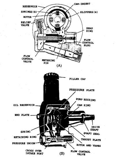
Fig. 27.70. Power steering pumps.
rounded by an oil reservoir, and the pump and reservoir are sealed with O-rings. These are positive displacement pumps. Each revolution delivers the same amount of fluid irrespective of speed of the pump. The pump capacity must be large enough to supply the fluid at required quantity and pressure during idling of the engine.
During operation, the rotor spins, causing centrifugal force to throw the vanes, slippers, or rollers outward due to which their outer surface maintain contact with the cam. Slippers usually have a back up spring to aid in maintaining cam contact. The cam fits the rotor closely at one or two opposite locations. The spaces between the vanes, slippers, or rollers gradually move outward as the rotor turns them past the close fitting point and the pump fluid flows from the reservoir into these expanding space through inlet passage. As the vanes, slippers, or rollers reach the widest part of the cam insert, they close the inlet passage from the reservoir and make contact with the pressure passage. Continuous turning decreases the volume between the vanes, slippers, or rollers, forcing the pump fluid into the pump pressure outlet passage. The power steering pump is connected to the power steering gear control valve with one high pressure hose and one low pressure return hose.
Power assist requirements become very high as the wheels are turned with the vehicle at rest. The engine is idling during this time, so the engine driven power assist pump is also running slowly. Power assist requirements are very low when driving at highway speeds and when pump speeds are fast. To compensate for high pump volumes at cruising
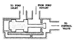
Fig. 27.71. Principle of flow control.
speeds, a flow control valve and a pressure relief valve are used.
Flow Control Valve Principle and Operation.
The passage from the pump outlet contains a restricting orifice. The difference in pressure drop across the- orifice increases with the increase of oil flow. High oil pressure from the upstream side of the orifice is directed at one end of the flow control valve and low oil pressure from the downstream side of the orifice is
directed at the other end of the valve. A calibrated spring is also located on the low pressure side of the flow control valve. The flow control valve, shown in Fig. 27.71, is operated by small pressure difference along with the calibrated spring.
With the increase of the engine speed from idle, both the pump flow and pressure increase. When flow reaches the maximum required value, the flow control valve moves towards its low pressure end and a passage between the pump outlet and pump inlet is opened, bypassing a portion of the fluid back to the pump inlet. With the increase of pump speed, the opening becomes larger, keeping the flow at the maximum required rate. Recirculating the oil back through the pump reduces the pump power requirement and keeps the oil temperature low.
Pressure Relief Valve.
Flow is restricted by the control valve when it sends fluid to one of the power chambers causing the pressure to rise. When the
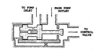
Fig. 27.72. Principle of pressure regulator.
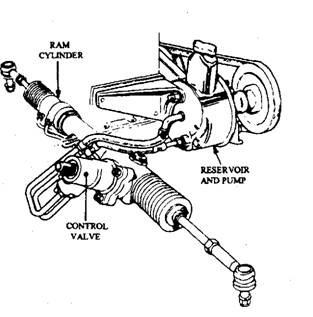
Fig. 27.73. Power-assisted steering layout.
driver turns the wheels against the steering linkage turning stops and continues to hold the steering wheel in the full turn position, pressure builds to a maximum. In order to avoid damage to the power steering unit seals and hoses, the pressure must be limited to a safe value and the pressure relief valve limits this pressure by opening a passage between the pump outlet chamber and the pump inlet or the pump reservoir. The pressure regulator normally is built into the flow control valve as shown in Fig. 27.72. If the pressure on the low pressure side of the control valve reaches a predetermined point, the pressure relief valve opens to allow oil to flow from the low pressure side of the flow control valve to the pump inlet. This drops the pressure in the low pressure side allowing pump output to flow freely into the inlet, thus lowering the pressure at the pump outlet.
27.8.5.
Rack and Pinion Power Assisted Steering
Figure 27.73 shows a rack and pinion power steering system. The engine-driven hydraulic pump is integral with the reservoir, and supplies oil to a control valve installed in the housing in which the pinion shaft is also mounted. The shaft in the steering column through a torsion bar provides motion of the control valve. The movement of the control valve directs oil to one side or the other of the ram piston attached to the steering rack.

Fig. 27.74. Spool control valve.
Figure 27.74 illustrates a simplified view of a rotary-type spool valve controlled by a torsion bar, placed between the steering shaft and the pinion of the steering box. The spool valve is a shaft having six flutes and is encased by a sleeve having six internal axial grooves. Oil from the supply line flows through the radial ports in the sleeve and shaft to the lines connected to the ram chambers. A series of splines between the shaft and sleeve limit the twist of the torsion bar to about 7 degrees in each direction. Therefore, the torsion bar is capable of transmitting the torque applied by the driver to the steering box pinion only up to 7 degrees on either side from central position. This fall-safe feature provides a mechanical drive from the steering shaft to the pinion during a failure of the power assisted system.
The amount of the torsion bar twist and the spool valve movement are proportional to the effort applied by the driver. Power assistance starts at about 0.5 degree deflection of the bar and this assistance rises till the bar moves to about 4 degrees, the point of maximum power supply. When the valve takes the no-power position (Fig. 27.74) all the ports open, and oil returns to the reservoir through the valve.
If the steering wheel is turned against a resistance encountered at the road wheel, the torsion bar is deflected so that the spool rotates relative to the sleeve. This cuts off the oil flow both to the reservoir and one side of the ram, but the other side of the ram is subjected to oil pressure. When this pressure builds up sufficiently, it moves the road wheel and brings back the torsion bar to the no-torque position. During this period, the oil displaced from the unpressurised side of the ram is returned to the reservoir. In case the resistance to road wheel movement is excessive, the oil pressure builds up to its maximum so that a relief valve, fitted adjacent to the pump, opens and allows oil to return to the pump inlet.
