24.2.
Plate Clutch
Figure 24.2 illustrates a simple plate clutch with a driven plate splined to the primary shaft of the gearbox. A pair of linings or facings made of an asbestos-based material is rivetted to the plate. The lining material is bonded with suitable resins to provide a satisfactory coefficient of friction and other required properties. The pressure plate is mounted with a number of studs, and is forced towards the flywheel by means of springs. A withdrawal sleeve permits the clutch pedal to act on the clutch forks and push the pressure plate away from the flywheel. An adjustable link is set to provide a small clearance between the clutch fork and the withdrawal sleeve so that the full force of the springs is applied on the driven plate.

Fig. 24.2. Single-plate clutch.
The pedal has a small amount of free movement due to clearance, which is about 25 mm when measured at the pad of the pedal. A spigot bearing, fitted at the centre of the flywheel, locates the front end of the gearbox primary shaft and allows for the difference in speed between the two members. This bearing can be of a ball race or plain bush. The ball race type is normally sealed with a metal cover to prevent splashing of the lubricant on to the linings. The plain bearing type is generally made of phosphor-bronze, and the bush is impregnated with graphite for self-lubrication.
When the pedal is pressed, the clutch forks push the pressure plate away from the flywheel so that the spring pressure is removed from the driven plate. This permits the plate to run free, and hence disengages the engine from the transmission. When the pedal is released, the spring thrust forces the pressure plate towards the flywheel, and sandwiches the driven plate between the two surfaces. This movement of the pedal must be gradual; otherwise sudden application of the full force of the springs to the driven plate causes a jolt.
When the pedal is fully released, the driven plate can follow two paths. It can either be transferred directly from flywheel face to driven plate, or can be taken through the studs and pressure plate to the rear face of the driven plate. The latter drive path requires close attention. An excessive clearance between any two parts in this drive path causes noise and a jerky operation of the clutch. This drive path is designed to take half the transmitted torque of the clutch. Therefore, modern units use more efficient layout to transfer the drive from the flywheel to the pressure plate.
During the engagement of the clutch, the force transmitted to the driven plate is required to be applied gradually. Since any jerky movement of the pressure plate provides a more pronounced judder at the road wheels, the flywheel/pressure plate connection must avoid, or limit the slip-grip action caused by friction at this point. The clutch in Fig. 24.2 is expected to suffer from this drawback, which is evident at a time when the pressure plate is moving towards the flywheel and driving torque is attempting to resist this axial movement, i.e. at a time when the vehicle is moving from rest.
The plate clutch is used today in most passenger cars and light trucks. When the driven assembly contains one clutch disc the clutch is known as single plate clutch. This has the advantage of producing a quick disengagement.
The double plate clutch is basically same as the single plate clutch except that another driven disc and an intermediate driving disc are added. Both driven discs are mounted on either same splined hub or two separate hubs. The driving disc and pressure plate are connected to the flywheel by parallel pins. The operating mechanism remains same.
Multi-plate clutch contains more than three discs. Due to higher frictional area through many number of plates, this clutch has a greater capacity to transmit power. It consists of alternate driving and driven discs. The driving discs are connected to the flywheel through a cylindircal housing having inner splines, which engage corresponding teeth on the rims of the discs. The driven discs are connected to the clutch shaft through splines. Multi-plate clutch is preferred with automatic transmission systems. Occasionally, it is also used on the expensive passenger cars and on trucks. Often, as many as eleven driving and ten driven discs are used for heavy trucks.
24.2.1.
Torque Transmitted

Though the value of u varies from point to point on the contact surface as it depends upon the relative velocity and the intensity of pressure, it is assumed to be constant for simplicity in calculations.
![]()
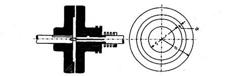
Fig. 24.3. Simplified representation of a single plate clutch.
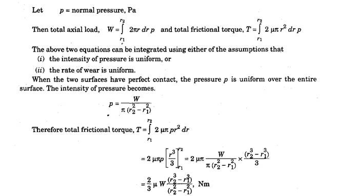
This assumption is normally used in situations involving power absorption by friction. This provides higher frictional torque than the case based on uniform wear.
On the other hand, the rate of wear depends upon the intensity of pressure as well as the rubbing velocity between the contact surfaces. Since the rubbing velocity is directly proportional to r, the rate of wear is proportional to pr. Hence, if the rate of wear is assumed to be constant, then pr ~ C. In case of power transmission by friction between two surfaces, this assumption gives better results. As the clutch is meant for power transmission in automobiles, considering uniform rate of wear, i.e. pr – C, total axial load becomes,
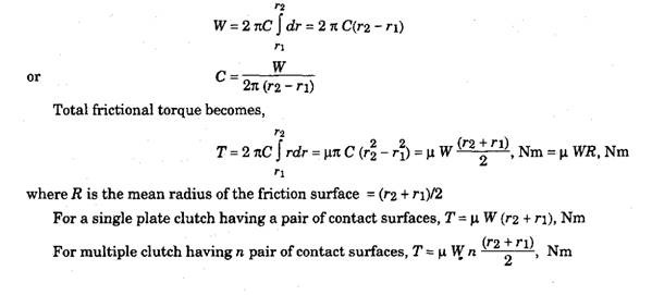
To have n pair of contact surfaces, there must be (n + 1) numbers discs or plates. If there are ua no. of discs on the driving shaft and ub no. of discs on the driven shaft, then the number of pairs of contact surfaces are n = ua + tib – 1.
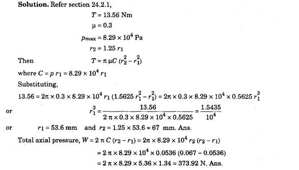
Example 24.1. An automobile power unit gives a maximum torque of 13.56 Nm. The clutch is of a single plate dry disc type, having effective clutch lining of both sides of the plate disc. The
coefficient of the friction is 0.3 and the maximum axial pressure is 8.29 x 10⁴ Pa, and external radius of the friction surface is 1.25 times the internal radius.
Calculate the dimensions of the clutch plate and the total axial pressures that must be exerted by the clutch springs.
24.2.2.
Energy Lost During Engagement
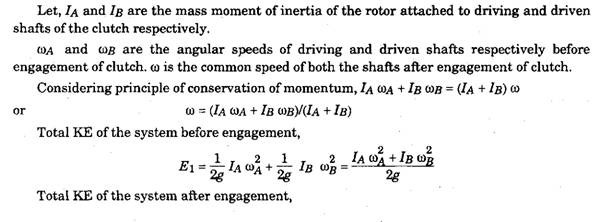
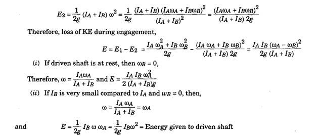
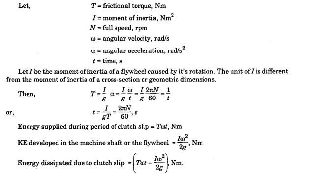
Energy Dissipated due to Clutch Slip
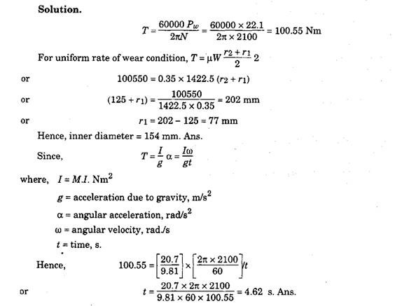
Example 24.2. An automobile is fitted with a single plate clutch to transmit 22.1 kW at 2100 rpm. The total axial load on the clutch plate is 1422.5 N. The outside diameter of the friction surface is 250 mm. Both side of the plate are effective and the n between the contact surfaces is 0.35. Assuming uniform rate of wear condition, calculate the inner diameter of friction surface.
The rotating parts attached to the driven parts of the clutch are initially at rest having M.I.
of 20.7 Nm2. Assuming the acceleration of the machine is uniform; calculate the time lapse before the engine attains full speed of 2100 rpm if the clutch is suddenly engaged.
