9.24.
Multi-point Mechanical Injection System
The Bosch K-Jetronic is a mechanical system, which uses the principle of continuous-flow fuel injection with air-flow sensing to meter the fuel. Figure 9.92 illustrates the basic system. A permanent magnet electric motor drives a roller type pump, which pressurizes the fuel sufficiently to operate the injectors. A pressure regulator valve limits the maximum pressure in the primary fuel circuit to 461 kPa, and excess fuel from this valve is returned to the tank. The spring loaded diaphragm, acting as an accumulator, (i) holds the pressure in the line to assist hot starting, (ii) slows-down the build up of pressure on starting, and (Hi) smoothes out the pulsations and reduces pump noise.

Fig. 9.92. Basic layout of a petrol injection system.
Fuel Distributor and Air Flow Sensor.
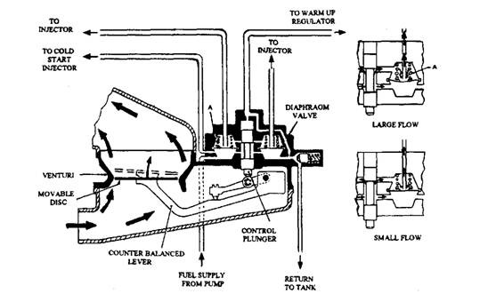
The air-flow sensor (Fig. 9.93) controls the quality of fuel delivered to the injectors. The sensor consists of a venturi with a movable disc and is fitted in the induction pipe. A counter-balanced lever attached to the disc, acts on a control plunger. A number of diaphragm valves, one for each injector, are mounted around the plunger. These valves supply fuel to the injectors, which is proportional to the movement of the control plunger.

Fig. 9.93. Bosch K-Jetronic fuel distributor and air flow sensor.
Once the engine is stationary, the disc rests in a closed position in the venturi whereas the lever and control plunger stay at the lowest position. Therefore no fuel passes from the waist of the plunger to the chamber above the diaphragm, and hence no injection takes place.
When the engine is running, the air movement through the venturi lifts the disc. The extent of the movement of the disc is controlled by the quantity of air flowing through the venturi. When the disc has moved a set value, the lever raises the control plunger and opens a slit, which allows fuel to the chamber. Although fuel pressure now acts on both sides of the diaphragm, but the force of the spring pushes the diaphragm downwards to open the valve at the centre of the diaphragm so that the fuel is released to the injector. The flow of fuel from the chamber slightly lowers the downward force on the diaphragm which allows reaching a set valve-open position that corresponds to the control plunger movement.
The throttle opening provides a greater airflow due to which the disc rises further, and in turn, raises the control plunger to allow more fuel to the chamber. This excess fuel flow is more than that escaping past the valve to the injector. Therefore, the extra downward force produced by the fuel pressure lowers the diaphragm, and opens the valve further due to which the quantity of fuel going to the injector increases.
The diaphragm unit acts as a differential pressure valve and regulates the pressure drop on each side of the diaphragm to a constant value of 14.7 kPa irrespective of supply pump
pressure, nozzle opening pressure or fuel flow. The air-fuel ratio in this system can be varied by altering the control pressure acting on the end of the control plunger. When this pressure is reduced, the sensor plate moves a greater amount for a given air flow resulting in a richer mixture.
Warm-up Regulator.
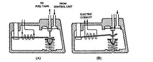
This regulator (Fig. 9.94) controls the mixture enrichment during warm-up period. It uses a valve operated by a bimetallic strip. The valve lowers the control pressure acting on the end of the control plunger when the engine is cold.

Fig. 9.94. Warm-up regulator.
A. Engine cold; Opening of the valve reduces pressure-opposing movement of control plunger.
B. Engine hot: During warm-up, electrical current heats bi-metal strip and gradually closes valve.
Cold Starting.
The cold starting system (Fig. 9.95) uses a cold-start injector located downstream of the throttle. This electrically operated valve, along with the auxiliary air device, operates when the thermo-time switch senses that the engine is cold.

Fig. 9.95. Bosch K-Jetronic continuous-flow fuel injection with airflow measurement. 9.24.1. Mechanical System with Electronic Control
The K-Jetronic system has been modified for closer matching of the mixture with changing loads and operating conditions to meet the stricter emission control regulations. The modified
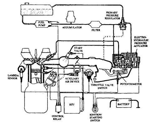
system is called Bosch KE-Jetronic. The letter E signifies electronic. When the mechanical system is controlled electronically, the mixture strength is set and varied more accurately to suit a wider range of operating conditions. The following are the silient features of KE-Jetronic system shown in Fig. 9.96 over the K-Jetronic system.
System Pressure Regulator.
More precise control of the system pressure is achieved through the modified regulator valve, which takes into account manifold depression.
Electro-hydraulic Pressure Actuator.
This performs as a fine mixture controller to vary the air fuel ratio precisely to meet all conditions of engine, especially during warm-up, acceleration and full-load operation.
Electronic Control Unit (ECU).
This acts as the brain of the system. It analyses the signals received from the throttle valve switch, air flow potentiometer, and engine speed and temperature sensors, and then sends output signals to the actuators, which control the fuel mixture.

Fig. 9.96. Bosch KE-Jetronic System.
Other additional feature included is the lambda closed-loop system, which allows the fuel to cut-off during over-run and control the mixture strength by using the variation in the oxygen content in the exhaust gas.
9.24.2.
Lambda Closed-loop System
The lambda sensor was first introduced by Bosch in 1976 and is essential for operation on a closed loop control. It is applicable to all engines, but it is virtually indispensable for those engines with exhaust systems fitted with catalytic converters. This is because, without closed-
loop control, unburned hydrocarbons can be discharged into the exhaust and be burned in the converter. Also, control is temporarily switched from closed to open loop when enrichment is required for cold starting, acceleration or maximum power operation.
In the closed loop control, the lambda sensor detects the deviations from complete combustion of all the air-fuel mixture supplied to a computer-controlled engine and signals back to the computer the onset of the changes, so that they can instantly be corrected. On the other hand, in an open loop control system the various parameters like coolant temperature, load and rotational speed are communicated to a control system, which is designed to keep the engine operating within the defined parameters. If, however, it drifts outside these parameters, the control system being unaware of these changes, cannot correct directly, and has to wait for signals from other, less precise indicators, like changes in engine temperature, speed, load or throttle opening to trigger appropriate control action.
The lambda sensor detects deviations from zero oxygen content of the exhaust. If the sensor shows the positive means the presence of oxygen that indicates inefficient combustion leading to either high specific fuel consumption and loss of power or, if indicates negative means presence of carbon monoxide and unburned hydrocarbons in the exhaust gas causing similar adverse effects on performance and exhaust emissions. Incidentally, the sensor has to be calibrated so that even with excess fuel at lambda 0.95, oxygen of about 0.2 to 0.3% by volume is still present in the exhaust gas. The lambda is the ratio of the actual mixture strength to that theoretically required for complete combustion of all the air and fuel.
The lambda sensor (Fig. 9.97) is enclosed in a steel housing, which is screwed into the exhaust maniflod, and its sensitive element is placed in the gas stream. This element is a zirconium oxide ceramic thimble, and its inner and outer surfaces are coated with micro-porous platinum to form electrodes. A louvered metal sleeve covers the thimble to screen it from erosion caused by solid particles in the exhaust gas stream.
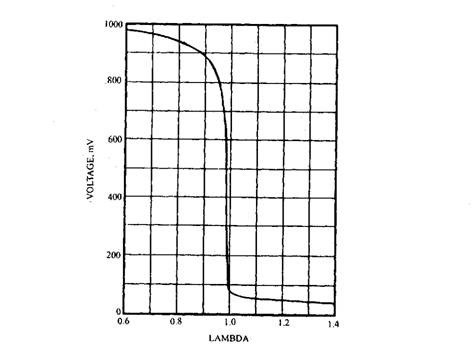
The outer surface is exposed to the exhaust gas stream, and the inner one to atmosphere. At about 573 K temperatures, the ceramic thimble begins to conduct oxygen ions. Any difference between the oxygen content of the gases exposed to the two platinum electrodes induces a voltage between them, which is proportional to the difference. The characteristics of the voltage difference can be tailored to suit the application. A typical example of the application is illustrated in Fig. 9.98. This type of sensor is extremely sensitive to deviations from lambda 0.1. Normally, the exhaust gas heats up the electrodes up to the temperature to become effective but, an electric heating element can be added for operation soon after starting at low temperatures.

Fig. 9.97. Bosch lambda sensor.

Fig. 9.98. Plot of voltage characteristic against air-fuel ratio of a lambda sensor at its normal operating temperature (about 873 K).
