9.25.
Multi-Point Electronic Injection System
A complete electronic system uses a solenoid-operated fuel injector, which works intermittently and opens at set times in the engine cycle. It remains open for a period of time, which is proportional to the quantity of fuel required. A number of different types of full electronic system are in use. The main difference among them is the method of measuring the air flow. The two main measuring systems are:
(i) Indirect or pressure-sensed air flow measurement.
(ii) Direct air flow measurement.
9.25.1.
Pressure-sensed Air Flow System
This system uses a manifold absolute pressure (MAP) sensor to measure the manifold depression. The ECU receives signals from the MAP sensor and, after analysing the data receiving from the other sensors, the ECU directs the injector to open for a set time, proportional to the quantity of air received by the engine.
Bosch D-Jetronic.
This system is an example of a pressure-sensed system (The letter ‘D’ stands for Druck, which means pressure in the German language). The basic layout of this type of system is shown in Fig. 9.99 where the quantity of air induced into the engine for a given throttle opening depends on the manifold pressure. A MAP sensor measures the manifold pressure and sends an electrical signal to the ECU to indicate the quantity of air entering the engine. After processing the signal, the ECU determines the period of time for the injector to remain open.
Commencement of injection is triggered by either a switch in the ignition distributor or a sensor placed adjacent to the flywheel or crankshaft pulley. For six-cylinder engines, the injectors are operated in sets of three, i.e. three injectors spray at the same time. Extra fuel
provision for cold starting is similar to that used in the K-Jetronic. The ECU receives messages from a number of sources (Fig. 9.100), and after processing the data as per the instructions programmed into its built-in memory, the ECU signals the injectors to operate accordingly. Some of the other items that are used to control the system are shown in Fig. 9.101. The throttle position switch works in conjunction with the MAP sensor for measurement of air flow.

Fig. 9.99. Basic layout of electronic system of petrol injection.

Fig. 9.100. Input and output signals of electronic system.
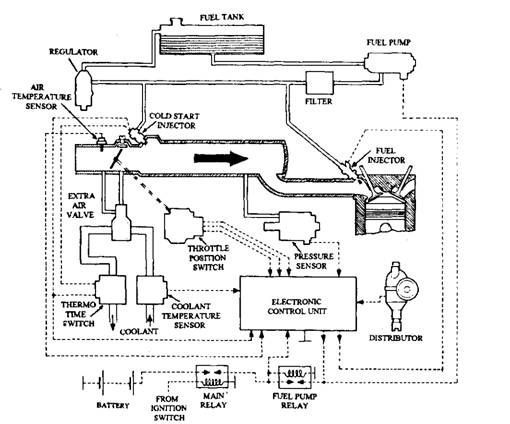
Fig. 9.101. Bosch D-Jetronic electronic system of fuel injection.
9.25.2.
Direct Air Flow System
In this system air, entering into the engine, is measured by vane (flap) or hot-wire metering. Both of these sensors produce voltage output, which is proportional to the rate of airflow. This voltage signal is passed to the ECU for computation of the fuel requirement, which is governed by the time period of opening of the injector. Both the sensors take into account of the actual density of the air entering the engine to compensate for variations in atmospheric temperature and pressure. This feature is especially significant to maintain the required air-fuel ratio when the vehicle operates at different altitudes.
Vane or Flap Metering. The layout of a system, shown in Fig. 9.102, is similar to a Bosch L-Jetronic. (The L stands for Luft, the German word for air). The flap sensor works in a similar way to a spring-loaded rigid flag, exposed to air movement. As the force on the flag increases with the air speed (or density), it moves through an angle to a position where the force of the air equals the reaction of the spring. In the case of the vane, the position it occupies for a given air flow is recorded by a potentiometer.
Other than the arrangement for sensing the air flow, the basic system is similar to one described previously. An electrically driven fuel pump produces fuel pressure, which is maintained constant at 196 kPa by a pressure regulator. Injector valves are actuated once in every crankshaft revolution and fuel quantity is controlled by the period of opening of the injector by the solenoid.
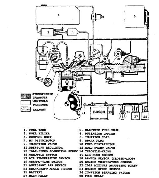
Fig. 9.102. Van or flap metering (Bosch LE-Jetronic).
Hot-wire Metering.
The principle of the system, illustrated in Fig. 9.103, is based on the cooling of a hot surface, due to air blown over it, and the rate of heat transfer depends on the rate of air flow. Both the Lucas EFI and the Bosch LH-Jetronic employ this method of air flow measurement.
The hot wire element of the sensor is heated by an electric current, which is sufficient to maintain it at a constant temperature. The cooling action increases with the increase of air flow, and therefore to maintain the temperature taking account of the losses, a larger current has to be passed through the wire filament. The voltage corresponding to this current provides an indication of the air flow. The ECU receives this voltage to compute the basic quantity of fuel, which is then slightly altered taking into consideration of the signals received from other engine
sensors.
!
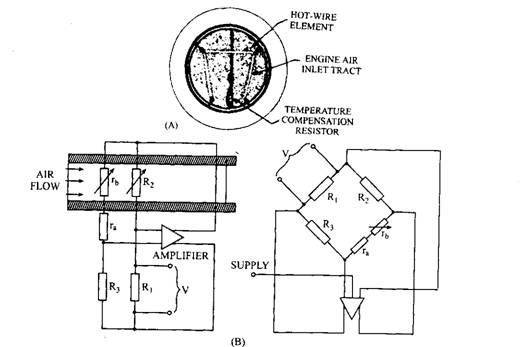
Fig. 9.103. Hot-wire sensing.
As the air temperature affects the accuracy of the system, a compensating resistor is placed in the air stream. A change in air temperature causes the resistor to alter its resistance, which compensates for the effect of a change of air temperature. Hot-wire sensing system controls air-fuel ratio within the limits required to meet emission regulations in force in various countries, and hence today this system is employed in many cars.
9.25.3.
Fuel System
Even though many different electronic systems of control are in use, the basic fuel supply system and the supporting electrical circuitry are often similar. A typical fuel supply system is now described to explain the basic principal of the main hydraulic components. Figure 9.104 shows the main components of the fuel system. The fuel supply system uses the injectors (described in section 9.26) with adequate fuel at a pressure sufficient for the injectors to provide good atomisation. The fuel pressure must not vary as the quantity of fuel injected depends on this pressure.
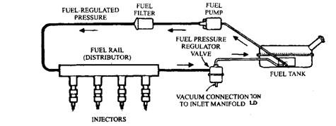
Fig. 9.104. Fuel System.
Pump.
Generally a roller-type rotary pump is used, which is operated by a permanent-magnet electric motor (Fig. 19.105). The rollers move outwards with the rotation of the pump and seal the spaces between the rotor and casing. Since the fuel is carried around with the rotor, the pressure increases due to the rotor movement combined with the decrease in volume of the pumping chamber. The pump supplies fuel through the motor to assist cooling. More quantity of fuel is supplied than required, and excess fuel is re-circulated back to the tank, which reduces the vapour lock problems.
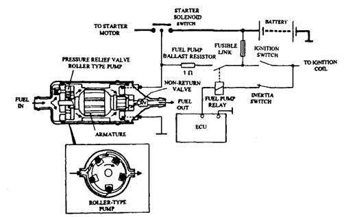
Fig. 9.105. Fuel pump and electrical supply circuit.
Two ball valves are installed in the pump; a non-return valve at the outlet and a pressure relief valve, to limit the maximum pressure. An ECU controls the pump through a pump relay, and the current to the pump passes through a ballast resistor to drop the voltage to 7 V. This resistor is shorted-out during engine cranking to compensate for the lower battery voltage.
The pump motor runs for a short period when the ignition is switched on, to fully pressurize the system. After this operation, the pump is stopped until the engine is cranked. As a safety measure, an inertia switch is installed in the electrical supply line to the pump relay. This switch opens if it is jolted, so when a collision takes place, the pump ceases to operate. The switch can be reset by pushing down a protruding plunger.
Fuel Pressure Regulator.
This regulator controls the operating pressure of the system and
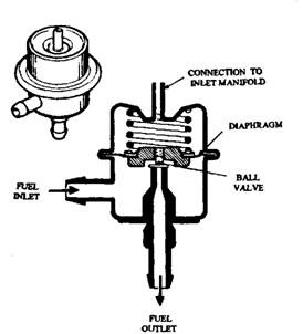
Fig. 9.106. Pressure regulator.
maintains a constant pressure difference of 245 kPa, the set value, between the fuel line and the inlet manifold irrespective of throttle opening. The regulator uses a spring-loaded diaphragm and ball valve (Fig.9.106).
Manifold depression depends on throttle opening e.g. engine load. When the throttle opening is small the high depression causes more fuel to leave the injector. This is compensated by lowering the fuel system operating pressure when the manifold depression is high. To achieve this, one side of the regulator is connected to the induction manifold. When the engine operates under a light load, the regulator valve is slightly opened to reduce the pressure. The regulator controls the pressure to 176.5 kPa when engine is idling with very high manifold depression and 245 kPa when engine is at full throttle with very low manifold depression.
