22.3.
Laminated or Leaf Springs
Due to low cost and simple connection to axle, the leaf springs are very popular for rear suspension. The most commonly used leaf spring is the semi-elliptic type, consisting of one main leaf, which usually has its ends formed into eyes for connection with the spring brackets, and a number of shorter leaves, the length of which gradually and uniformly decreases from the main leaf. The various leaves are held together by a centre bolt. The main details of a semi-elliptic spring are presented in Fig. 22.7. To obtain a constant stress throughout the spring the leaves are graduated in length. Rebound clips transmit the load to some of the lower leaves during the return motion of the spring, and thus eliminate the need for using large number of leaves above the main plate. Rubber bushes, fitted in each eye, allow for movement of the spring, and act as noise insulators. A swinging shackle accommodates the alteration in spring length.
The force required for unit deflection of a spring is called the stiffness or rate of the spring. The stiffness of a spring depends on the
(i) length of spring (shorter spring, higher stiffness),
(ii) width of leaf (wider spring, higher stiffness),

Fig. 22.7. Laminated or leaf spring.
(Hi) thickness of leaf (thicker spring, higher stiffness), and (iv) number of leaves (greater number, higher stiffness).
A low-rate spring gives soft ride but it also deflects a larger amount under a given load. Normal springs have a constant rate, and produce a deflection, which is proportional to the load (Hooke’s Law). When the lower leaves are set to a reverse camber, a stiffening-up of the spring occurs with the increase of deflection. This is called a progressive or variable-rate spring.
As the laminated spring deflects the plates or leaves slide over each other causing inter-plate friction. This provides beneficial damping effect, but also causes ‘hard’ ride, noise and wear, which necessitates reduction of this friction as much as possible. To achieve this, nowadays special features are incorporated with the spring instead of periodic spraying of penetrating oil, done earlier. These include,
(i) Fitting the synthetic rubber buttons at the ends of the leaves.
(ii) Reducing the number of leaves, this however requires the increase in the width. (Hi) Using inter-leaf plates of low friction material.
Today many springs in use have only one leaf. This is a tapered leaf, which is thin at the ends and thick in the centre, so that overstressing at the centre of the spring is avoided.
22.3.1.
Classification
Laminated leaf-spring configurations may be classified by the portion of an ellipse they represent i.e. fully, three-quarter, half, or quarter elliptic. Application of original fully elliptic spring (Fig. 22.8A) refers to the days of coaches, but now it is used only for the suspension of commercial-vehicle driver-cab. The three-quarter-elliptic spring (Fig. 22.8B) gives a soft but more rigid support. This configuration in a modified form provides a progressive dual-rate fixed cantilever spring whose stiffness increases with loading. Therefore it is used on some heavy recovery vehicle having a considerable weight difference between unladen and laden conditions.
The most commonly used leaf spring today is the half or semi-elliptic spring (Fig. 22.8C). It is used for car rear suspension and for both front and rear suspensions of van and lorry. The quarter-elliptic springs (Fig. 22.8D) is used on small sports cars where a compact short spring is preferred. Transverse semi-elliptic springs (Fig. 22.8E) are commonly used to form bottom, top, or both transverse link-arms for both front and rear independent suspensions. The cantilever-mounted semi-elliptic spring (Fig. 22.8F) has been used in some cars such as the Jaguar for the rear suspension. The central pivot of this spring extends the effective spring length. The spring lies parallel and very close to the chassis, so that a compact and effective suspension is achieved.

Fig. 22.8. Laminated-spring configurations. A. Fully elliptic. B. Three-quarter-elliptic.
C. Half-or semi-elliptic. D. Quarter elliptic.
E. Transverse-mounted semi-elliptic. F. Cantilever-mounted semi-elliptic.
22.3.2.
Design Features
When the springs are manufactured, each leaf is curved or given a camber set. The smallest leaf receives the maximum set, which is progressively reduced with the increase of the span of the leaf, so that the main leaf has the least set (Fig. 22.9). A centre bolt is used to align and clamp the various leaves together. For holding the leaves together along their span, they are clamped with steel clamps (sometimes rubber-lined) at about halfway between the centre bolt and the spring eyes.
During multi-leaf spring deflection, the upper side of each leaf tip slides or rubs against the underside of the blade above it. This inter-leafs action creates friction, which may be useful under certain conditions, as it reduces the amount of bounce, but normally it does not match the ride characteristics required and it makes the suspension too stiff, so that harsh riding over light road irregularities is experienced.
Inter-leaf rubbing in the presence of moisture causes fretting corrosion, which decreases the fatigue strength, so that the oscillating life of the spring is also reduced. This problem can be reduced to some extent by applying phosphate paint between the blades. Also by fitting a thin layer of lead or an anti-friction disc between the blades (Fig. 22.10), the fiction in the interference and hence fretting can be reduced.
The top surface of each leaf is shot-peened or work-hardened to prolong its life. This process changes the stresses on the upper side of the blade from a normal tensile to a compressive state so that the fatigue life of spring-blade is greatly improved. Rounding the edges of the blades also reduces risk of fatigue failure. Further by changing from a straight cropping
of the blade ends (Fig. 22.10) to a tapering of the leaves near their ends (Fig. 22.11), the stresses within the blade are more evenly distributed along each blade span. This reduces the peaking of stress level so that spring life is increased. At present, leaf springs are mostly made from silicon mangangese steels.
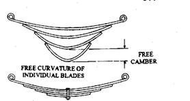
Fig. 22.9. Combined curvature of clamped blades.

Fig. 22.10. Straight-cropped blade ends with disc inserts.

Fig. 22.11. Taper-cropped blade ends.
22.3.3.
Methods of Mounting to the Chassis
The following are the two basic methods of mounting a semi-elliptic spring to the chassis.
Constant-rate Swing Springs.
With this type of mounting (Fig. 22.12), the forward end of the spring is directly pinned to the front spring-hanger and the rear end to a swing shackle. During deflection of the spring between the unloaded and the loaded position, the spring camber is reduced and the spring length increases. To achieve this, the swing shackle has pivot about the upper fixed shackle-pin so that the driving thrust is transmitted through the forward half of the spring directly to the fixed spring-hanger. As the spring straightens out, there is very little change in the spring stiffness, and hence this is known as a constant-rate suspension spring.

Fig. 22.12. Constant-rate fixed and swing leaf springing.
Progressive-rate Slipper Springs.
With this type of arrangement (Fig. 22.13), the forward end is pinned directly to the front spring-hanger as before, but the rear ends has no eye and it just rests on a curved slipper block or pad. When the spring is unloaded, the contact point lies on the out side position of the slipper face, but as the spring is loaded, the straightening of the spring rolls the main-leaf end around the slipper profile from the outer to the inner position. This effectively shortens the spring length, which is equivalent to stiffening the spring. Therefore this offers a progressively increased resistance to the vehicle payload.

Fig. 22.13. Progressive-rate slipper-block-contact leaf spring.
22.3.4.
Shackle Arrangements
For an efficient suspension, the vehicle weight is transmitted to the leaf spring through a fixed hanger at the front end of the spring and generally a swinging shackle at the rear end. The spring is hinged at each end by shackle-pins, which provide a firm joint but can rotate or pivot in rubber or metal bushes. This does not alter the suspension and steering geometry as the spring deflects and the various forces act on the system. This also reduces wear and noise. Rubber bushes are generally used for cars and vans, and metal phosphore-bronze bushes are provided on heavy-duty commercial vehicle.
Rubber Bushes.
Two types of rubber bushing commonly used are flanged rubber half-bushes (Fig. 22.14A) and silent block rubber bushes (Figs. 22.14B and 22.15A ). Normally the silent block bush is fitted at the fixed hanger end, and a split flanged bush acts as the bearing for the swinging shackle used in small and medium-sized cars. In large cars and vans, the silent block joint is used at each end of the leaf spring.
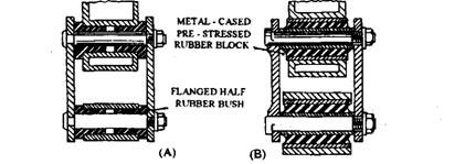
Fig. 22.14. Swinging-shackle arrangements with rubber bushes. A. Plain rubber-bushed joint. B. Silent block rubber joint.
Flanged rubber half-bushes (Fig. 22.14A) are pushed into the chassis holes and are then clamped together until the shackle side-plates are firmly held against the shackle pin shoulders. The twisting motion of the spring, if any, is absorbed as a torsional straining of the rubber. The inside and outside rubber provide friction grip when they are in compression, so that no relative slip between the rubber and metal takes place.
The silent-block-type rubber bush (Fig. 22.14.B and 22.15A) uses an outer and an inner steel cylindrical case and the rubber is in pre-stressed condition in the bush, so that there is no relative slip between the rubber and the steel casings. Any relative twist is taken up as torsional elastic strain. The outer casing is a force fit in the spring eye or chassis hole, but the shackle-pin is a slip fit during assembly. To prevent the inner casing from rubbing relative to the pin, the shackle side-plates are tightened up until the shoulders of the tube casing are hard against the plates.
Metal Bushes.
The metal bushes (Figs. 22.15B and 22.16) are used for heavy duties. These bushes can either be plain or screw-profiled, and both types are a force fit in the spring eye or spring mounting hanger. To minimize rubbing between the shackle-pin and the metal bush, the bushes are always lubricated through holes drilled axially along the shackle-pin. A radial intersecting hole in the middle of the pin permits the passage of grease between the pin and the bush. Plain bushes usually have internal helical grooves so that the grease spreads more evenly over the bush bearing surface.
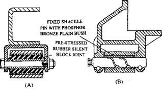
Fig. 22.15. Fixed-shackle arrangements. A. Rubber-bushed joint. B. Plain metal joint.
Heavy-duty suspension uses more robust shackle pin and plate clamping (Fig. 22.16). One of the two most common arrangements is the taper shackle-pin, which wedges the two parts firmly together when clamped to the shackle-plate. The other is the slotted-shackle-plate and bolt with an alignment groove machined at each end of the pin.
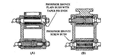
Fig. 22.16. Swinging-shackle arrangements with metal bushes. A. Plain rubber-bushed joint. B. Screw metal-bushed joint.
22.3.5.
Forces Acting on a Semi-elliptic Suspension
In a semi-elleptic leaf-spring suspension, static and dynamic vertical loads are absorbed by the chassis mounts, springs and axle (Fig. 22.17A and B). The driving thrust (Fd) and the braking retardation (Fb) are absorbed between the axle and the front hanger mounting through the forward half of the spring span. The acceleration torque (Ta) and the braking torque (T&) are absorbed by distortion of the leaf spring. During acceleration the reaction torque (Tr) tends to twist the axle clockwise and the vertical reaction force (Fr) tends to lift the front end of the chassis and pushes the rear end into the ground. While braking, the torque reaction tends to rotate the axle anticlockwise, pushing the front end down and raising the rear end. All side-forces are absorbed by the spring blades, shackles, and chassis.

Fig. 22.17. Acceleration and braking reaction forces acting on the spring shackles. A. Acceleration reaction. B. Braking reaction.
22.3.6.
Semi-elliptic Multi-leaf Spring
A multi-leaf spring has several leaves laid out side by side forming a triangle or placed on each side of the main leaf forming a diamond shape (Fig. 22.18). The length of each leaf is such that the total cross-sectional area of leaves at any point is proportional to the bending stress at that point. Therefore this produces a constant stress across any section along the full spring span.
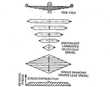
Fig. 22.18. Multi-leaf parallel-section spring.
A centre bolt placed through a hole drilled at the centre of each leaf clamps the leaves together, but reduces the cross-section of the spring-leaf at the mid-point, which results in a slight stress peak on the stress-distribution graph (Fig. 22.18). Since the main leaf eyes do not have a triangular reduced section, but a parallel square section, the stress near the eyes is tapered off.
22.3.7.
Single Trapezium-shaped Leaf Springs
A single trapezium-shaped leaf spring also maintains an approximately cosntant stress distribution along the entire spring span. This constitutes a single spring blade, which has uniform thickness but its width increases from ends towards the mid-span (Fig. 22.19). This increase in cross-sectional area counteracts the increase in bending moment causes by the body weight, so that the spring is uniformly stressed along its length.
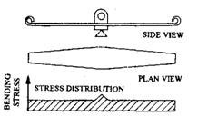
Fig. 22.19. Single trapezium-shaped leaf spring.
22.3.8.
Single- and Multi-taper Leaf Springs
Use of a single-leaf spring-blade of constant width, but its thickness decreasing from a maximum in the mid-span position to a minimum at the ends is more common (Fig. 22.20). The proportionally enlarged cross-sectional area of the blade resists the increased bending moment from the spring end to the centre. Since the taper leaf is more compact and easier to clamp on the axle-beam, it is preferred to the trapezium shape.
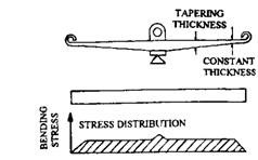
Fig. 22.20. Single tapered leaf spring (parabolic).
For heavy-duty vehicles, two or three taper-leaf springs are used together. To avoid touching of the springs at any point between the middle seat section and the load-bearing end points (Fig. 22.21), liners may be used between the pressure points.
22.3.9.
Advantages of Taper Leaf Over Multi-leaf Springs
The following are the advantages of taper-leaf over multi-leaf springs:
(i) The weight of a single-leaf spring with variable cross-section is about half that of multi-leaf spring used for the same payload.
(ii) A single taper leaf does not have inter-leaf friction. Even with multi-leaf taper spring, inter-leaf friction is reduced because of fewer leaves and these leaves bear upon each other only at the ends. This provides a better ride.
(Hi) The stresses in taper-leaf spring are more uniform and overall lower than with the
multi-leaf type. This provides longer life to taper-leaf spring. (iv) With the single-taper-leaf spring, no inter-leaf collection of moisture and dirt take
place, so that fretting corrosion and fatigue failure are minimized.
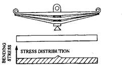
Fig. 22.21. Multi-taper leaf spring.
