9.26.
Injector
The injector delivers a finely atomised spray of fuel downstream into the throat of the inlet port. In addition, the injector must vary the quantity of fuel to suit the engine operating conditions and this is achieved by varying the time of opening of the injector. The required conical spray pattern is obtained by pumping the fuel through a pintle-type nozzle. Solenoid operates the nozzle valve (Fig.9.107) to affect fuel flow. Movement of the valve is limited to about 0.15 mm and the period of opening the valve varies from about 1.5 to 10 milliseconds (0.0015 to 0.01 second).

Fig.9.107. Fuel injector.
This change in opening time varies the amount of fuel supplied to each cylinder per cycle. The opening time depends mainly on the rate of air flow and engine speed; however engine temperature and fuel temperature also have a bearing on the required amount fuel to be delivered. All injectors are electrically connected in parallel. When the engine is warm, injector opening normally occurs once every other revolution. When the engine is cold-started, frequency of injection is increased to inject extra fuel. Injector opening and closing are carried out by a solenoid and spring respectively.
Greater accuracy of metering of the fuel become essential to meet the demands for lower fuel consumption with better performance, and to fulfil stringency of emission control due to which several injectors are currently being used. For precision electronic metering of fuel supplied to the engine, a linear relationship between quantity of fuel delivered and pulse width, over its full range from maximum (the pulse repetition period) to zero is a primary essential. This would imply both instantaneous starting and stopping of flow, and a linear relationship between quantity of fuel delivered and time.
Practically, there is a lag between the beginning and end of the electronic control pulse and the actual starting and stopping of the flow of fuel. Because of this, the point of zero delivery is offset along the time axis from the origin (Fig. 9.108). Except for pulses of very short width, it
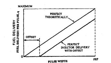
Fig. 9.108. Fuel delivery vs. pulse width.
is possible to arrange linear flow from start to finish, up to but not including the pulse repetition point. At the latter point, the flow is continuous so, in effect, the start is no longer offset from the origin.
The difference between the shortest linear pulse width and the offset is termed the minimum linear duration of injection. This must be as small as possible, to maximise the dynamic range of delivery of the injector. The dynamic range is defined as the ratio of maximum to minimum duration of injection. Ideally the point of origin should coincide with the point of zero delivery, so that the dynamic range becomes infinity.
Within the characteristic limits of the injector, the maximum duration of injection is basically a function of the rotational speed of the engine and the number of times (once or twice) the injector is fired per revolution. On the other hand, the minimum duration of injection is determined to a major extent by injector design and the consequent offset of the delivery characteristic.
Linearity of injection improves with the ratio of the actuation force to the mass delivered by the valve as well as with the appropriate matching to them of the electrical and time constants of the solenoid circuit. Since the time required for closing the injector is a function of the current in the solenoid at the point of breaking its circuit, delivery errors are difficult to eliminate when the pulse width is shorter than required to allow the current to build up to a stable value.
Injector firing strategies can be either sequential, which is one injection for every two revolutions, or simultaneous double-fire, which is one injection per revolution of the engine. The electronic control system is simpler for simultaneous double fire than that for sequential injection, and therefore less costly. The sequential firing strategy is generally used only for turbocharged and other high performance types of engine. These normally require high ratios of maximum to minimum linear deliveries of fuel, or a large dynamic range. It is because injection at narrow pulse widths with a simultaneous double fire system may cause operation in the non-linear range leading to poor driveability.
9.26.1.
The Lucas Injector
The Lucas D-series injector (Fig. 9.109) meets all these requirements. Instead of a pintle, it uses a disc type armature held down on the valve seat by a coil spring and the fuel pressure. It
is designed for fuel pressures from about 170 to 390 kPa, and flows from 80 to 400 g/min. The electronic control energises the solenoid and, when the build up magnetic force exceeds the force exerted by its return spring plus the hydraulic pressure, the armature is lifted from the seating ring around the valve port (Fig. 9.110) until is stopped by the shim above. When the solenoid
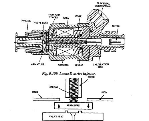
Fig. 9.110. Armature deflection limited to the distance between the valve seat below and a shim above.
circuit is broken, the current decays until the spring force exceeds and closes the armature on to the seating ring, which is further supported by the additional force exerted on it by the fuel pressure.
As presented in Fig. 9.111, the mass of the armature disc may be an eighth of that of a pintle and between a third and a quarter of that of a spherical seating valve so that the force (mass ratio) also correspondingly increases, and therefore also the rate of acceleration of the armature. Consequently , the zero point of the delivery line (Fig. 9.107) shifts towards the origin. The D-series injector can be operated in the linear range with a simultaneous double fire strategy. This is possible because, at static flow rates of less than 250 g/min, and a pulse repetition period of 10 ms, it has dynamic range greater than 20:1. The D-series injector has the typical resis-

Fig. 9.111. Comparison between effective of three injector valve types.
A. Pintle type, 4.0g. B. Ball type, 1.8 g.
C. Lucas CAVarmature, 0.5 g.
tance values for the solenoid coil winding as 2.35 ohms for current mode systems and 16.2 ohms for voltage mode operation.
Some earlier designs have experienced the accumulation of deposits in the delivery orifices of injectors. These deposits generally contain carbon, and hydrocarbon gums and varnishes. As they build up, there is a gradual shift towards lean mixture and partial blockage, causing progressive loss of power, misfiring, surging and poor driveability.
Pintle type injectors can be noisy, up to about 57 dB(A) overall and 62 dB(A) maximum. But, due to the low mass of the plate valve of the D-series unit, the noise level is about 9 dB(A) quieter overall with the engine stopped and the injectors cycled, reducing to about 2 dB(A) with the engine running. Although leakage can adversely affect both engine start times and emissions, but with the flat disc of the plate valve seating on a flat surface in the Lucas injector, tight sealing is assured.
The spray at the induction valve must be aimed accurately for obtaining low HC emissions at full load. With a single hole the normal spray pattern is a cone with 10 degrees included angle
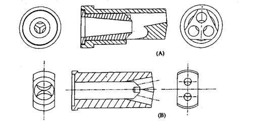
Fig. 9.112. Alternative nozzles.
A. Top, three hole, wide angle cone jet.
B. Two hole divide jet for 4-valve heads.
and this is adequate for most applications. Lucas use spray director inserts in the injector nozzle (Fig. 9.112) to produce sprays of different forms.
9.26.2.
The Bosch Injectors
The light weight injector valves used in the Bosch K- and KE-Jetronic systems are opened at relatively low fuel pressure of about 325-355 kPa, acting on their heads, the actual value, however, depends on the engine application and fuel quality. They vibrate axially at a frequency of1500 Hz to atomise the fuel, which is continuously injected into the manifold. When the engine is stopped, they return to their seats by light springs (Fig. 9.113). The vibration is initiated due to the sudden increase in an area exposed to the opening pressure, as the valve first lifts off its seat. Since this is instantly followed by an equally sudden local release of pressure it seats again. The complete process is repeated cyclically until the ignition is switched off and consequently the injection pressure drops.
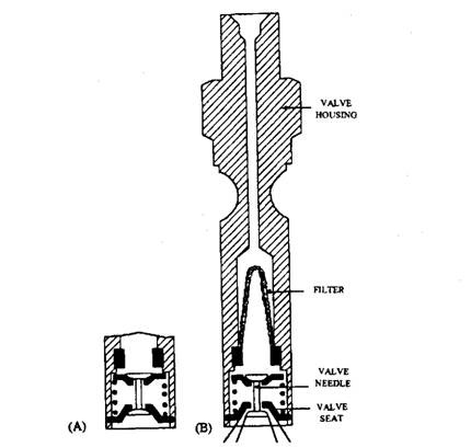
Fig. 9.113. Injector for K-Jetronic system. A. Valve closed. B. Valve open.
Some of the Bosch injectors are air shrouded (air jacketed) around the injector body. Its upper end is connected to a pipe from the air intake, and its lower end is opened to the induction manifold around the nozzle. The manifold depression induces a flow of air through the jacket around the fuel spray directed at the inlet valve which helps atomisation and evaporation, specifically with the K-and KE-continuous injection systems.
Injection valves are heavier for the L-Jetronic variants and Motronic systems shown in Fig. 9.114 and 115 respectively as well as their return springs. This is because they are integral with the armatures of the solenoids, which open them for timed periods. These solenoids are energised by the electronic control unit. The valve lifts are 0.1 mm and the pick-up and release times between 1 and 1.5 ms.
After passing through a filter at the top of the injector, fuel flows down in both systems through slots in the sides of the armature into a chamber in the tip of the valve. Consequently, the lifting of the valve is accelerated due to
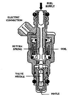
Fig. 9.114. L-Jetronic injector.
sudden exposure of the area of the needle seating face to the delivery pressure. A collar located towards the upper end of the needle limits its axial travel. Atomisation is assisted by a head ground on the tip of the pintle of the L-Jetronic injector.
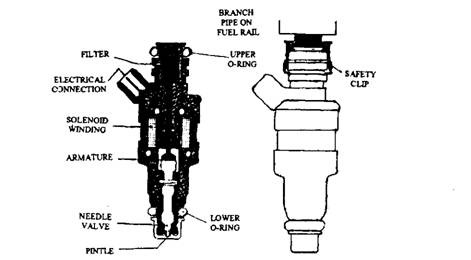
Fig. 9.115. Nose of the Motronic injector, with an O-ring seal around it, is a push fit in a boss in the induction manifold.
The injector used in the Motronic system is designed to clamp down the fuel rail directly on to its upper end. The needle uses a polished straight flanked pintle on its tip, and the fuel atomises as it passes through the precision hole in the nozzle. A needle lift of 0.1 mm and break-away and release times of 1.0-1.5 ms are normally used.
Generally the Bosch injection valves, including those with air shrouded are not screwed into the manifold. Their noses and the upper ends of their bodies are both push fitted in rubber rings.
The lower ring seals the boss in which the injector is carried in the manifold and the upper one is held in a hole in a bracket. In case of screw type connection, hexagon shape collars are made near the upper ends of the injectors for holding them in a spanner. The rubber rings protect the units from excessive vibration and insulates them against heat, to avoid formation of vapour bubbles locally in the fuel, as this can cause difficulties in hot starting the engine. To avoid deposition of fuel spray in the manifolds, the jets are aimed at the valves in the inlet ports .
Cold Start Valves. Bosch use start valves in all their multi-point systems, whereas most other manufacturers incorporate the electronic control unit to signal the injector to supply the extra fuel needed for cold starting. The Bosch start valve for the KE-system is shown in Fig. 9.116. The unit for the L- Jetronic is similar but more compact. Its fuel inlet, with a filter, is located on the side of the unit,
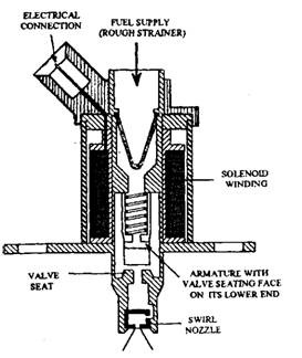
Fig. 9.116. Cold start valve shown open.
the solenoid coil and armature are shorter, and the electrical connection is made at the upper end of the unit. The start valve sprays fuel into the induction trunk instead of into the inlet valve ports. They are of the form of an injector valve, but of less sophisticated design.
