25.21.
Hydraulic Control of Actuators
The clutches and brake bands of most automatic gearboxes are operated by hydraulic means. A pump, driven from the torque converter at the engine speed generates the fluid pressure to lock the clutch plates or brake drum. Distribution of pressurized fluid to the clutches and brakes is carried out by a control valve, called a manual valve, linked to the driver’s selector lever. Although many types of valves are incorporated in automatic gearboxes, the basic principle of operation of each vale is the same. The construction and operation of some of the valves are now considered.
25.21.1.
Regulator Valves (Relief Valves)
The relied valve limits the hydraulic line pressure to a set maximum. Three main types of this valve illustrated in Fig. 25.49 include ball, piston and spool.

Fig. 25.49. Types of regulator valve.
Ball and Plunger-type Valves.
These valves are similar to those used on automobile engines. When the pressure acting on the valve produces a thrust greater than the force exerted by the spring, the valve lifts and prevents any further increase in the pressure (Thrust = Pressure x Area).
Simple Spool Valves.
These valves are similar to the plunger type except that they are waisted (reduced in area at the centre) to control the fluid flow. Since the effective areas of A and B are the same in Fig. 25.49, the pressure in the waist region exerts an equal thrust upwards and downward, due to which the pressure in this region can not cause the movement of the valve. When pressure in the system is sufficient to lift the valve, a port is uncovered. Fluid then flows to the waisted part of the valve from where it is either returned to the reservoir or passed to a line that acts on another part of the system.
Differential Spool Valves.
These valves have two spool plungers of different diameter similar to the type illustrated in Fig. 25.50. As fluid pressure starts to build up, the spool moves to the right, because the effective area of B exposed to the fluid is larger than that of A. However, the extent of movement of the spool depends on the spring strength. The spring is located in a chamber which is vented so that a pressure build-up behind the valve is avoided. When the

Fig. 25.50. Simple pressure regulator valve.
pressure reaches a set value dictated by the spring, the spool uncovers the port C so that the fluid is spilled out preventing any further rise of pressure.
25.21.2.
Control Valves
This type of valve directs the fluid to a hydraulic line to activate or control the appropriate clutch and/or brake.
Manual Control Valve.
This valve is connected by rod or cable to the driver’s selector lever, so its position is governed by the gear position set by the driver. A very simple manual valve used to control forward and reverse movement of a vehicle is shown in Fig. 25.51. In this illustration, the lever operates the valve and uncovers the port that connects to either the forward or reverse gear actuators. Positive location of the valve is obtained by a selector ball detent arrangement.
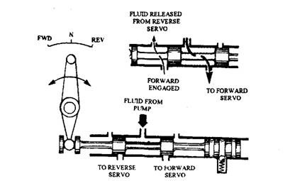
Fig. 25.51. Simple manual valve to control forward and reverse gears.
Pressure Sensitive Control Valves.
For the automatic control of the gear changes, it is necessary to sense the speed of the road wheels. A hydraulic system of control mounts a governor on the output shaft for sensing the speed. The governor generates a fluid pressure, which increases with the rise of road speed. Control valves installed in the governor fluid circuit sense the circuit pressure. At the appropriate time, the valve operates and directs the fluid through the lines to engage the new gear.
A spool valve with a fluid connection at each end is illustrated in Fig. 25.52A. If the areas of the faces A and B are equal, the valve moves to the right when the fluid pressure at C is
greater than at D and vice versa. It remains in a central position when pressure at C equals to the pressure at D. The fluid pressure existing at E has no effect on the movement of the valve because the thrust tending to move the valve to the right is balanced by an equal and opposite thrust acting on the other face. In many ways this is similar to the action of the two springs. If the area of one spool is made larger (Fig. 25.52B) the pressure acting on the larger area provides a greater thrust on the valve than that given by similar pressure at C.
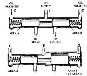
Fig. 25.52. Spool valve controlling flow to either servo or clutch.
25.21.3.
Basic Hydraulic System
The hydraulic system discussed in this chapter does not represent on actual system used in any particular make of automatic transmission, but it illustrates the basic principles of automatic control by using a much simplified system. With this basic information the reader should be able to comprehend the construction and operation of a modern unit. The operation of the system is considered in a series of stages.
Stage 1 Layout.
Figure 25.53 illustrates a simple fluid supply system, which operates a clutch and torque converter.
Pump.
Normally an internal-external gear pump is used, which is driven at engine speed from tangs formed on the torque converter casing. The fluid from the reservoir passes to the pump through a fine screen-type filter where any small dirt particles are arrested. Most modern automatic gearboxes use only one pump at the input. Therefore it is not possible to start the engine because the engine and pump are stationary, hence pressure is not generated in the system to activate any clutch and brake so that neutral results.
Primary Regulator.
This speed spool valve controls the line pressure, applied to the manual valve. In the system illustrated, the line pressure always remains constant. This is unsuitable for a modern gearbox because the high pressure required to prevent slip under conditions of high torque gives harsh changes when the engine is lightly loaded. Fluid released from the valve is fed to the inlet side of the pump instead of discharging into the reservoir. This arrangement saves energy to draw fluid through the fine-mesh filter screen.
Secondary Regulator.
Since line pressure is too high for the converter, the secondary regulator acts as a pressure reducer. A portion of the fluid returning from the converter passes either to an oil cooler, or to a line that provides low-pressure lubrication of the gearbox.
Manual Valve.
As per the directive from the driver this valve distributes the fluid to the various valves, clutches and brakes. In the position shown in Fig. 25.54, the fluid is delivered to the front clutch at line pressure.
Sequence of Clutch and Brake Application.
The order in which the clutch and brake actuators are applied depends on the type of gear train. The example under discussion has a driven range as presented in Table 25.3.
Table 25.3. Clutch and Brake Operation.
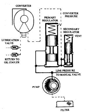
Fig. 25.53. Hydraulic circuit-stage 1.
| Gear | Front Clutch | Rear Clutch | Brake Band |
| D, | Yes | No | No |
| D2 | Yes | No | Yes |
| D3 | Yes | Yes | Yes |
The table indicates that all the three gears in the drive range use the front clutch ; the particular gear in this range is determined by the actuation, or non-actuation, of the rear clutch and brake. Use of the front clutch in this manner is common to many other gearboxes. Since the application of the forward clutch is only carried out when the vehicle is stationary, the wear on the forward clutch is minimal unlike the rear clutch.
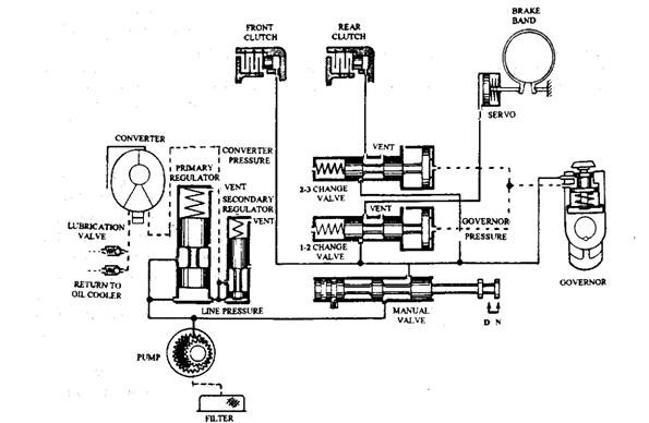
Fig. 25.54. Hydraulic circuit-stage 2.
Speed and Load Sensing.
Gear changes are made when a predetermined road speed is reached. Therefore, some form of sensor is necessary to inform the gearbox when to change the gear.
Speed Sensing.
Automatic gearboxes use one of the following devices to determine the speed of the output shaft.
• Mechanical governor.
• Hydraulic governor.
• Electronic speed sensor.
The speed sensor must work in conjunction with a shift valve (change valve), which directs the fluid to the clutches and servos to change the gear when a predetermined road speed is attained.
Mechanical Governor.
This centrifugal system uses two bob-weights, which throw out against the resistance of a spring as the speed of rotation increases. The governor is driven from the output shaft, and movement of the flyweights causes the operation of a hydraulic spool valve, which directly governs the gear changes. Today this system of speed sensing is practically obsolete with automatic transmission.
Hydraulic Governor.
This governor has been developed from the mechanical governor. A spool valve used in the system is sensitive to a centrifugal effect produced by its rotation. As a result it generates a fluid pressure, which increases with speed.
Electronic Speed Sensor.
This type of speed sensor incorporates a magnetic sensor fitted close to the output shaft of the gearbox. Signals from the sensor are passed to an ECU for processing so that the data can be used for electronic systems such as the gearbox control.
Stage 2 Layout.
This stage (Fig. 25.54) uses an additional set of change valves and a hydraulic type governor compared to the stage 1 layout.
Change Valve.
Out of two valves illustrates in Fig. 25.54, one valve controls the up and down changes between first and second (1-2 shift valve) and the other changes between second and third (2-3 shift valve).
A simplified shift valve is presented in Fig. 25.55. Line pressure from the manual valve acts at port A and the line supplying the appropriate clutch or servo is connected at port B. Movement of the valve against the spring takes place due to pressure of the fluid from the governor at port C. When the governor pressure is sufficient to overcome the spring tension, the shift valve moves and connects port A with port B. This allows line pressure to act on the servo or clutch so as to reduce the change of gear. By attaching a stronger spring to the 2-3 shift valve (or making the valve relatively smaller in area), the 2-3 valve is made to open at a much higher governor pressure than the 1-2 valve.
The diameter of the plunger D is larger than that of plunger E. This feature prevents a gear hunting action after the valve has opened. Gear hunting causes severe vibration of the vehicle due to the oscillation of the shift valve between the open and closed positions. Once the valve starts to open, the extra thrust on piston D is added to the thrust provided by governor pressure due to which the valve is opened fully. This arrangement causes the up-changes to occur at higher road speeds than the down-changes.

Fig. 25.55. Gear change (shift) valve.
Hydraulic Governor.
This type of regulator valve alters the fluid pressure in the governor line corresponding to the road speed. The line pressure rises with the increase of road speed. The principle of operation of a hydraulic governor is illustrated in Fig. 25.56. A valve is mounted in the governor body and a bob-weight slides in the centre of this valve. A spring pushes the valve outwards, i.e. towards the bob-weight. This design provides a two-stage characteristic. As indicated in the graph, the high-pressure rise, in relation to a small speed increase during the first stage of its operation, provides good sensitivity so that the 1-2 gear change always occurs at the same speed.
At speeds less than about 500 rpm the operation of the first stage takes place. During this stage the bob-weight and valve act as a solid unit, so that as the bob-weight moves outwards and inwards the valve opens and closes the supply port.
The change in governor output pressure is achieved by the action of the fluid pressure on face A. An increase in speed causes the valve to move outwards due to which the supply port is opened. This increases the fluid pressure acting on face A until it produces a sufficient thrust to move the valve inwards and close the supply port. A further increase in speed causes this operation to be repeated, but the greater centrifugal effect due to increased speed requires a higher pressure in the valve chamber to close the supply port.
The second stage starts when the bob-weight stop contacts the governor body. From this point onwards, the balance between the opening and closing of the valve is achieved when centrifugal force on the valve equals thrust of fluid on face A.
Operation of Stage 2 Layout.
The automatic selection of three gears can be achieved with the layout shown in Fig. 25.54. When “D” is selected, the manual valve supplies line pressure to the front clutch and with the aid of a free wheel, first gear (Di) is obtained. Line pressure is also applied to the other valves in the system, but all of these valves are inactive. As soon as the vehicle moves, rotation of the output shaft produces a governor pressure, which acts on both shift valves. At a speed controlled by the strength of the spring situated in the 1-2 shift valve, the governor generates sufficient pressure to open the valve, so that line pressure acts on the brake servo to give second gear (D2).
With a further increase in road speed, the governor pressure rises further until it reaches a point where it overcomes the stronger spring in the 2-3 shift valve. At this speed the opening of the 2-3 valve causes line pressure to act on the rear clutch and provide third gear (D3).
Load Sensing.
The road speed at which the up and down gear changes occur varies with the load of the engine. That means the speed at which the gear changes occur increases with movement of the accelerator pedal. This feature mimics the techniques used by a driver i.e. light
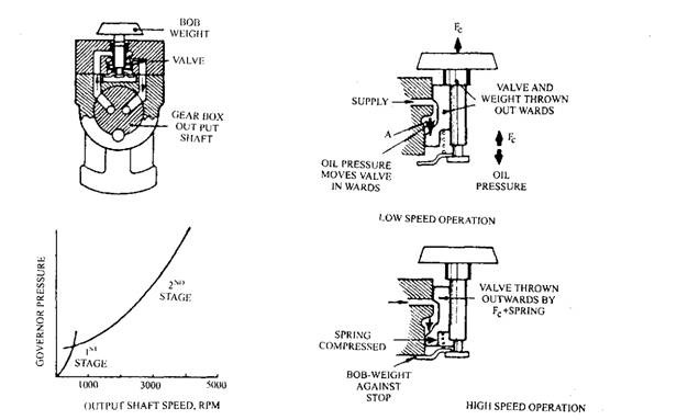
Fig. 25.56. Governor operation. throttle pressure, early changes, heavy throttle pressure, and delayed changes.
Most automatic transmissions use one of the following:
• Manually operated throttle valve. • Vacuum-operated throttle valve.
• Electronic control.
Manually Operated Throttle Valve.
This valve produces in, a separate line, a fluid pressure, which increases as the accelerator pedal is depressed. This throttle pressure is applied to one end of the shift valves, and opposes the governor pressure that acts on the other end of the valves so that the point at which the shift valve operates is altered.
The throttle valve is normally operated by a cable, which connectes a lever on the side of the gearbox to some part of the carburettor throttle linkage. As the throttle is opened the cable is pulled. This pulling action rotates a cam in the gearbox and compresses a spring, which acts on the valve.
Stage 3 Layout.
This layout (Fig. 25.57) illustrates how a simple throttle valve, positioned in the fluid system, controls flow and pressure to the throttle line.
When the throttle is closed, line pressure from the manual valve cannot pass the spool of the throttle valve. If the throttle is opened to a certain amount, the spring on the cam side pushes the valve to the right. This partially uncovers the port connecting the manual valve, and allows fluid to spill past the throttle valve to generate a pressure in the throttle line. A connection between this line and the chamber at the end of the throttle valve causes pressure to be felt behind the valve. As pressure builds up, the valve moves slightly to the left. This reduces the flow from the main line until a balance is reached, as with many other valves, between the valve opening and the output pressure.
Depressing the accelerator further down repeats this sequence, but the increased spring thrust, caused by the new position of the cam, requires a greater pressure in the throttle line to balance the valve. As the throttle is depressed more, the pressure in the throttle line becomes more.
Besides acting as the main controller of speed changes, the throttle line pressure can also be used to vary the line pressure to suit the load on the engine. To achieve this throttle pressure is applied to the end of the main regulator valve.
Vacuum Operated Throttle Valve.
Inlet manifold depression provides a better indication of the engine load. Therefore, some automatic transmission systems use a throttle valve, which is controlled from a vacuum chamber located on the side of the gearbox.
Electronic Control.
A sensor, controlled by either manifold pressure or throttle position, signals the engine load to an ECU. After processing the signal, the ECU energizes a solenoid to move the appropriate shift valve and change the gear. Some gearboxes along with this control system also use a vacuum chamber, connected to the manifold, to vary the line pressure to suit the conditions.
Kick-down Valve.
On the occasions, such as overtaking, a driver requires acceleration. In an automatic transmission system this is achieved by full depression of the accelerator pedal to a position called kick-down. In a simplified basic system (Fig. 25.57), a movement of the pedal to this position opens a kick-down valve in the hydraulic system so that a sudden drop in pressure in the throttle line occurs. Up to a certain speed in each gear position, this drop in pressure produces an immediate down-change of gear. In the figure the kick-down valve is positioned
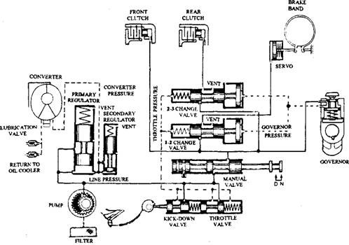
Fig. 25.57. Hydraulic circuit-stage 3.
between the throttle valve and the cam. When the pedal is fully depressed the cam moves the kick-down valve to the right to increase the pressure in the throttle line.
