28.11.
Hand Brake or Parking Brake
While the foot-brake system retards or stops a moving vehicle, the hand brake system prevents the vehicle moving once it is parked. Since the hand-brake system may be in operation for very long time period, a linkage mechanism separate from that of the hydraulic foot-brake circuit is installed. Parking brakes are generally provided only on the rear road wheels.
28.11.1.
Hand Brake Linkage Layouts
Either cable or rod linkage is used in a hand brake system to link the various components together. The general trend is to use a cable for cars and vans, and rods only for heavy duty commercial vehicles. The braking effort in both cases is transmitted from the hand brake lever to the rear wheels by tension, in contrast to a hydraulic foot brake circuit, that works in compression. Various hand levers are interchangeable to suit the car’s configuration.
Sliding-equalizer Hand-brake Cable Layout.
This arrangement transfers the hand lever movement to a sliding equalizer through a single primary cable. The middle of the secondary cable is looped around the curved equalizer, and each end of this cable is connected to the brake lever of one side wheel (Fig. 28.63). The hand brake lever can be adjusted by a nut screwed on the threaded end of the primary cable.
An outer cable cover supports and guides the secondary cable. The cover is usually fixed to the car’s underbody structure at one end. During the application of the hand brake lever, the primary cable pulls the middle of the secondary cable. The secondary cable slides relative to the equalizer around a specially formed semicircular groove, so that any difference in length or slackness between the two halves is equalized. Consequently this action provides an equal tension to each rear brake lever though both halves of the secondary cable.

Fig. 28.63. Sliding-equalizer hand-brake cable linkage layout.
Swing-link-compensator Hand-brake Cable Layout.
A pull-twist handgrip (Fig. 28.64), when applied, transmits leverage to the primary cable, the rear end of which is connected to a T-shaped lever. The tension in the primary cable rotates the T-lever due to which the two short perpendicular arms pull the two transverse cables connected to the rear-wheel parking brake levers. The swing link compensates any uneven slack in the two transverse cables and applies equal braking force to the parking brake levers.

Fig. 28.64. Swing-link-compensator hand-brake cable linkage layout.
Another compensator mechanism uses a roller mounted to the swing link. One short transverse cable is connected between the swing link and one of the wheel parking brake levers. The other long cable connects the opposite wheel parking-bratfe lever to the swing-link roller, turns at right angles, and then runs parallel with the wheelbase to the hand-brake lever. Application of the hand lever pulls the long primary cable decreasing the cable span between the swing link roller and the wheel lever. This action initially compensates any slackness in the opposite separate cable, and then applies equal braking force in both transverse cables and hence the corresponding parking brake levers.
Roller-and-relay-lever-compensator Hand-brake Cable Layout.
A pull-squeeze pistol-grip pulls the primary cable, which is guided to the cranked relay lever at the rear of the car. The cranked relay lever with the roller wheel attached at one end takes up the slackness of the single secondary transverse cable by pushing this cable at some point near its centre span. This gives an equal pull to both wheel parking-brake levers. The length of one or both cables (Fig. 28.65) is altered to carryout adjustment.
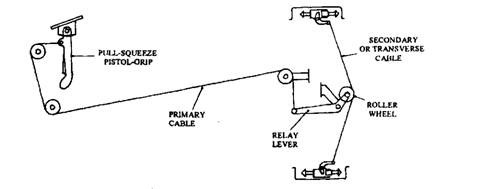
Fig. 28.65. Roller and relay-lever-compensator hand-brake cable linkage layout.
28.11.2.
Hand-brake Lever Mechanisms
Hand-brake lever assemblies are used to apply or release the parking brakes. These assemblies may also be designed to provide additional leverage to the system. Pull-squeeze Palm-grip Hand-lever.
This mechanism uses a rectangular box section tube bolted to the dashboard. A draw bar is fitted in this tube and it has a spring loaded pawl and an actuator strut. The pawl engages a ratchet made on the underside of the box tube. For applying the parking brake, the driver pulls the handgrip lever out and releases his grip. Consequently the pawl slots into the adjacent ratchet-tooth space and holds the cable in tension (Fig. 28.66). To release the brakes, the driver pulls the handgrip and squeezes the release lever. As a result the push rod forces the actuating strut to clear the pawl from the ratchet teeth. The hand palm-grip is then moved forward so that the brakes are released.
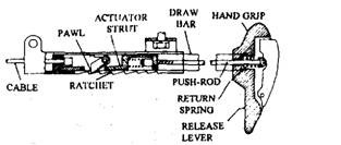
Fig. 28.66. Pull-squeeze palm-grip and release hand-brake lever.
Pull-twist Handgrip Lever.
This arrangement uses a circular draw bar with ratchet teeth cut on one side. Two pawls engage these teeth. A peg, inserted near the lower end of the bar, limits the free twist movement to about 90 degrees. For applying the parking brake, the handgrip is twisted to move the ratchet teeth away from the pawls. This action causes the pawl edges to come in contact with the smooth surface portion of the draw-bar. When the bar is pulled out
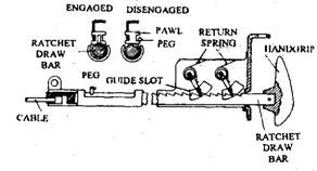
Fig. 28.67. Pull-twist handgrip and release hand-brake lever.
and then twisted back to its original position, the ratchet teeth is placed adjacent to the pawls allowing them to engage the nearest tooth so that the brake cable is held in tension (Fig. 28.67).
Pull-press-button Hand-Lever (Light-duty).
This construction, the most popular type at present, uses a hand-lever. One end of the hand lever is connected directly to the brake cable while the other end forms the handgrip, with a release press button. This lever is pivoted on a ratchet bracket. When the driver pulls up the lever arm, the spring-loaded pawl slides over the ratchet teeth causing maximum cable tension. At this point the lever is released, and the vehicle park-pulls up the hand lever slightly
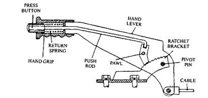
Fig. 28.68. Pull-press-button hand-brake lever and release (light-duty).
ing brake is applied. To release the parking brake, the driver to relax the tension on the pawl, and then presses in the press-button with the thumb, so that the pawl teeth are rotated clear of the ratchet teeth. This causes the hand lever to returns fully down to the released position (Fig. 28.68).
Pull-squeeze Pistol-grip Hand-lever.
In this design, the piston-grip hand-lever is pivoted on the ratchet plate. To obtain leverage, the cable is connected relatively close to this pivot point. When the hand lever is pulled, the spring-loaded pawl just slides over the backs of the ratchet teeth providing maximum tension to the cable. Now the pistol-grip is released, and the slight forward movement pushes the spring-loaded pawl into engagement with the nearest ratchet tooth. To release the parking brake, the release trigger is squeezed and the hand-lever is drawn back slightly. This makes the pawl free allowing it to rotate and clear the ratchet teeth. The lever is then pushed forward fully to the released position (Fig. 28.69).
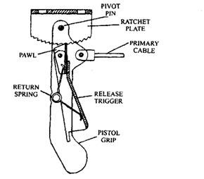
Fig. 28.69. Pull-squeeze pistol-grip hand-brake lever and release.
Pull-press-button Hand-lever (Heavy-duty).
This construction uses longer upright lever arm than incorporated in the light-duty arrangement for obtaining more leverage. The ratchet plate, pivoted at one end, is free to swing down and bear against the pawl. When the hand-lever of the parking brake is applied, the pawl lifts the ratchet plate up and allows the pawl to slide underneath the teeth until the parking position is reached. Then the hand lever is released so that the pawl immediately engages the nearest ratchet-plate tooth. To release the brakes, first the lever is pulled back, then the press button is depressed to move the pawl away from the ratchet teeth, and finally the lever is moved forward towards the released position (Fig. 28.70).
