9.22.
Gasoline Injection
The major advantage of any type of fuel injection system is accurate control of the quantity of fuel injected into the engine. The basic principle of a fuel injection is that if gasoline is supplied to an injector at a constant differential pressure, then the amount of fuel injected is directly proportional to the injector open time.
Modern gasoline injection systems are controlled electronically, due to which the fuel quantity and quality can to be accurately set to suit the engine operating conditions. Strict emission control regulations require accurate metering of the fuel. In spite the gasoline injection systems are more expensive; these are now commonly used on engines designed for high output.
A gasoline injection system, which delivers the correct quantity of highly atomised fuel at each inlet valve of the engine, provides the following advantages, when compared with a normal carburettor and manifold layout.
(i) Lower exhaust pollution.
(ii) Lower fuel consumption. (Hi) Higher power output.
(iv) Smoother engine operation due to an even power output from each cylinder.
(v) Uniform supply of anti-knock additives to each cylinder.
(vi) Automatic adjustment of the air-fuel ratio to suit operating conditions.
Gasoline injection was used first time in the 1899 Gorbron Brille car, which had a spline-driven rotary fuel injection pump. For cars, injection was not seriously considered until after World War II when, as early as 1946, Mercedes was developing it for production cars. The Hilborn Travers continuous injection system was used on an Indianapolis racing car engine in 1948 and in 1951, the Goliath 2-stroke engine used direct injection into the cylinders. Subsequently in 1953, the indirect injection was introduced in the Connaught racing engine.
By 1954, Mercedes fitted in their 300 SL and some of their racing cars with a Bosch direct injection system based on the use of a cam-and-plunger of jerk type pump. Two years later in 1956, a pump-less system was invented by Bond to reduce the high costs of injection. Also the year 1956 witnessed the major change in the history of gasoline injection due to the introduction of the Bendix Electrojector, on which practically all the modern systems are based. This system was based on the then state-of-the-art of electronic control technology that had been first experimented with in 1932 by the Atlas Diesel Co. and later, in 1940, by Caproni-Fascaldo.
In 1960, a Lucas injection system using shuttle valves was introduced, but no mechanical system could compete against fast evolving hydraulically and electronically controlled systems. In fact, the subsequent advances on the original Bendix concept, initially by Bosch from 1967 onwards, and later by Weber, GM, and Lucas, could not have been possible without the developments in electronics and computer control systems that have since taken place.
By 1957 Rochester had developed the Electrojector for continuous injection on the Chevrolet production cars. The Lucas shuttle valve system went into production for the Maserati V 8
engine in 1958, and the Bosch system on a Ferrari Formula 1 racing car in 1961. In 1962, an interesting jerk pump system developed by Kugelfisher was introduced into some Peugeot production cars, and Lucas injection was installed on several racing cars. The Tecalemit-Jackson injection system was introduced in 1964. Some years later, in 1968, this was taken up by Brico, but soon dropped because the Bosch electronically controlled system became most successful. In the same year, however, the Spica system was incorporated to the Alfa Romeo Montreal.
The introduction of the Bosch D-Jetronic injection system on VW and other cars in 1968 was the commercial break through and led a away for the establishment of the subsequent developments. The next major advancement in the electronically controlled injection system was the development of the Lambda sensor by Bosch. This device is used for detecting the presence of oxygen in the exhaust. This device enabled the control to be exercised on the closed loop principle, which is essential for satisfying the requirements of the latest emissions regulations.
9.22.1.
Injector Positions
Injection systems can be divided into two main groups; multi-point and single-point. This classification is based on the number and positions of injectors (Fig. 9.86).

Fig. 9.86. Layout of gasoline injection systems. A. Multi-point injection. B. Single point injection.
(a) Multi-point injection uses separate injectors for each cylinder, and each injector is located close to the inlet valve of the engine.
(6) Single-point injection uses only one injector, which discharges fuel into the: air stream at the point used by a carburettor.
Injecting the fuel into a pre-chamber increases the complexity of the cylinder head, reduces the space available for valves, and introduces losses due to both thermal conduction and throttling of the gases in the passage interconnecting the prechamber and the cylinder. With both indirect injection into pre-chambers and direct injection into the cylinders, the hydraulic pressure has to overcome the compression pressure in the gas, which is high, causing noise, consumption of more power by pump and possibly, fuel leaks. Another disadvantage is that the time available for completion of injection, evaporation and mixing after injection is very short.
Injecting fuel into the manifold or some other part of the induction system overcomes all these problems and due to the presence of low pressures, dribbling of fuel from the injectors is much easier to avoid. Additionally, because injection can start before the inlet valve is opened,
it provides more time to fuel to evaporate into and mix with the air than if it is to be injected directly into the cylinder.
If the fuel is injected into the inlet ports in the cylinder head, it can easily be directed at the hot inlet valves, so that evaporation becomes faster. Additionally, there is little possibility of condensation on the walls of the manifold, especially if the engine is warm; hence fuel acceleration, distribution and consumption are improved. Manifold design is also much simplified. However, the cylinder head casting may become complicated to accommodate injectors in it.

Fig. 9.87. Indirect petrol injection.
9.22.2.
Multi-point Injection
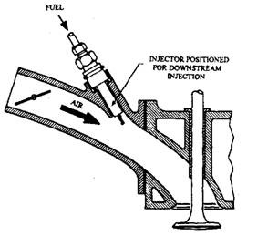
As explained above, indirect injection is preferred (Fig. 9.87). In this arrangement an
injector, operating at a low pressure e.g. 196 kPa, is fitted close to each inlet valve to spray the fuel downstream into the air as it passes the valve of the engine. Because fuel spray needs only a comparatively low pressure, a simple injector construction is sufficient. The injector body is screwed into the manifold, which encloses a spring loaded conical valve that chatters to break up the sray. A pipe made of plastic material supplies fuel to the injector.
Petrol injection can be timed or continuous. In the timed injection fuel is sprayed into the air stream only when induction occurs. Although a manifold is not essential in these arrangements, it is still used to accommodate an air cleaner and throttle valve.
Continuous injection is simple and of low cost when compared with timed or phased or sequential injection. With low pressure continuous injection, the fuel is injected unceasingly into the manifold or ports, premixing it with air to form a cloud of rich mixture just upstream of the inlet valves, ready for induction into each cylinder in turn. Once a valve opens, this rich
mixture is swept by the incoming air into the cylinder, where swirl and turbulence convert it into an ignitable mixture.
In continuous flow systems, air-fuel ratio can be controlled by varying the pressure of the fuel delivered to the injectors. But, with many such systems, there is a short time lag for affecting the required changes in air-fuel ratio after receiving signals from the control unit. A better alternative is to maintain the injection pressure constant and vary the volume of fuel delivered by incorporating a flow control valve, or fuel distributor. When such systems are equipped with electronic control, the mixture can be appropriately and accurately enriched for cold starting, acceleration and development of maximum power.
In timed injection, in which control over air-fuel ratio, is carried out by regulating the duration of flow through the injector, or timing it. Generally in such systems, all the injectors open and close simultaneously but, partly because their response is virtually instantaneous. Extremely close control can be achieved over air-fuel ratio, though at cost. The fuel can be injected into either the manifold or, much more commonly, its branch pipes or directly into the ports. This type of system is attractive for the middle range saloon cars.
With timed injection the duration is limited, and also the start of injection through each injector is phased relative to the opening of the inlet valve of the cylinder that it serves. This further reduces the possibility of transfer of fuel from the cylinder under serving into another. Also, control can be extremely accurate.
An advantage of both timed and phased injection into the ports of manifold branch pipes is ease of integration of the electronic controls to regulate injection and ignition for avoiding detonation. Either a single detonation sensor operating in conjunction with a crankshaft angle-of-rotation sensor, or a sensor for each cylinder or pair of cylinders can provide a signal to the electronic control unit (ECU) indicating which cylinder or cylinders are detonating. Corrections are then applied by such a system either to enrich the mixture supply or modify the ignition timing for the individual cylinder or cylinders that are detonating. Obviously, optimum emission quality is obtained by applying the corrective measures to only the cylinder or cylinders that are detonating.
The advantages of close control over fuel supply are the avoidance of overheating of a catalytic converter in the event of ignition failure in one or more cylinders, and the exercise of closer control over emissions, with both timed and phased injection, it is relatively easy to enrich the mixture appropriately for starting, acceleration, and the development of maximum power. Phased injection is specifically attractive for high performance and luxury cars.
9.22.3.
Single Point Injection
The single-point injection can be into either the induction manifold or the throttle body. The latter is sometimes referred to as throttle body injection (or TBI) and the former as central fuel injection or single point injection (CFI or SPI). With TBI, not only the injector but also the injection control unit is usually integrated with the throttle body. Otherwise the fuel may have to be delivered through an external pipe, instead of a short duct, to the injector.
Single point injection systems face the problems associated with carburation. These problems mainly are unequal mixture distribution, and the deposition of fuel on, followed by its controllable evaporation from, the walls of the manifold with variations in manifold pressure. The throttle body heating becomes necessary to avoid icing as well as to assist evaporation and mixing. However, when the whole injection system and throttle valve are installed together as
a single compact sub-assembly, the throttle body injection becomes significantly less costly than a multi-point system. Therefore, it is perhaps most suitable for the competitively priced small saloon or fleet cars.

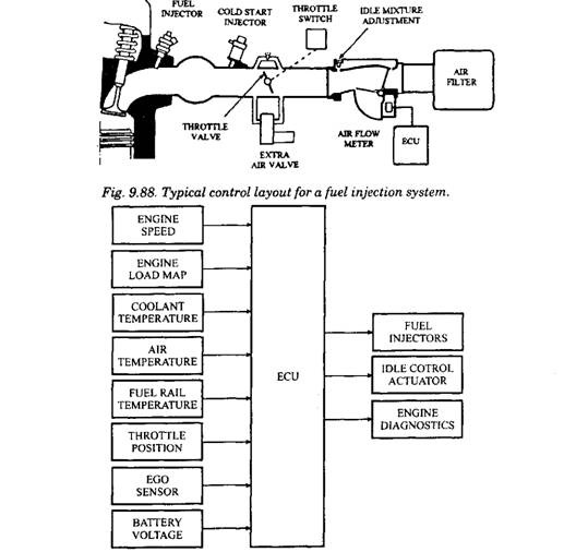
Fig. 9.89. Block diagram of inputs and outputs common to most fuel injection systems.

Fig. 9.90. A three dimensional cartographic map.

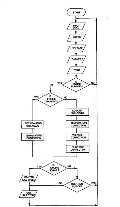
Fig. 9.91. A flow chart to determine the optimum injection open duration and control of engine idle speed.
