9.7.
Fuel Gauges
Gauges are generally more expensive than indicating lights. Gauges indicate the values of important parameters required to be known by the driver for smooth, trouble free and safe operation of the vehicle, such as remaining fuel etc. The gauges have different designs and are mostly electrically operated. In one type of design shown in Fig. 9.32 a coil of resistance wire is
wound around a bimetal arm. The movable end of the arm is connected by a linkage to an indicator needle, which shows the value against a scale panel placed behind the needle.

Fig. 9.32. Typical instrument circuit using thermostatic heating.
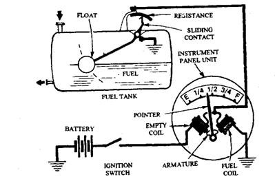
Another type of design uses a balanced coil principle as shown in Fig. 9.33. A series coil carries full instrument current. The current then splits, part going to a variable resistance in the sending unit and the rest going to the shunt coil. High resistance in the sending unit increases the shunt magnet strength and a low resistance weakens the magnetic strength. Current flowing through the sending unit changes as its resistance changes. The indicator needle is deflected by the difference in the magnetic strength of the sensing and shunt coils.

Fig. 9.33. Typical instrument circuit using balanced coil.
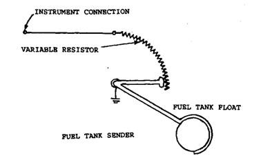
The sender unit in these cases is the fuel tank, which connects the instrument electrical system to ground; thereby it directly connects to the negative side of the battery to complete the circuit. In the fuel gauge sending unit, a variable resistance rheostat is connected to the hinged tank float (Fig. 9.34). When the fuel level is high, the gauge circuit connects directly to ground, allowing full current to flow through the instrument coil, which moves the instrument needle to the top of the scale. As fuel is used, the float drops, this causes the instrument circuit current to flow through part of the variable resistance adding resistance, reducing current flow. On thermal instruments this reduces instrument coil temperature, so the gauge reading lowers. In both the cases, gauge reading is proportional to the tank fuel level. The instrument gauge
mechanism is sensitive to current flow; therefore, it is important to have a constant voltage source for attaining accuracy. In these instruments generally supply is made from a vibrating point voltage regulator, which may be a separate unit or part of the fuel gauge level that keeps the voltage at a constant value, usually 5 V. The schematic wiring diagram for a balanced coil fuel gauge system is shown in Fig. 9.35.

Fig. 9.34. Schematic of the sending unit.

Fig. 9.35. Schematic wiring diagram for the fuel level gauge.
