27.9.
Four-wheel Steering (4WS)
The front-to-rear wheel alignment plays a significant role in the directional stability of a vehicle. Often the lack of stability causes a dangerous drive. This is clearly observed when a car has worn suspension bushes. Up to the mid-1950s the majority of cars suffered from over-steer, mainly due to the uncontrolled movement of the rear axle caused by spring deflection which is initiated by body roll. The problems associated with an over-steer characteristic are now well understood. To improve stability, most cars nowadays are designed to exhibit under-steer characteristic when driven at high speeds.
One step in obtaining an under-steer characteristic is to use body roll movement to steer the rear wheels. This is achieved either by misaligning the rear axle or by changing the geometry of the suspension system in the case of the car fitted with independent rear suspension. Although under-steer condition improves stability of the vehicle, it increases the driver’s steering effort. Also since a vehicle handling changes with road speed, the response to a steering movement, both in time and direction, is difficult to predict.
These disadvantages can be overcome to a great extent by using four wheel steering (4WS). Two car manufacturers, Honda and Mazda, introduced 4WS on some of their models in 1988. Compared with a conventional two

Fig. 27.75. 4WS wheel angles (angles shown are exaggerated).
wheel steering system, the advantages offered by a 4WS system include :
(i) Superior cornering stability.
(ii) Improved steering responsiveness and precision. (Hi) High speed straight line stability.
(iv) Notable improvement in rapid lane-changing manoeuvres.
(v) Smaller turning radius and tight-space manoeuvrability at low speed. 27.9.1. Relative Wheel Angles and their Control
The direction of steering the rear wheels relative to the front wheels depends on the operating conditions. At low-speed wheel movement is pronounced, so that rear wheels are steered in the opposite direction to that of front wheels (Fig. 27.75). This also simplifies the positioning of the car in situations such as parking in a confined space. Since the rear wheels are made to follow the path on the road taken by the front wheels, the rear of a 4WS car does not turn in the normal way. Therefore the risk of hitting an obstacle is greatly reduced.
At high speed, when steering adjustments are subtle, the front wheels and rear wheels turn in the same direction. As a result, the car moves in a crab-like manner rather than in a curved path. This action is advantageous to the car while changing lanes on a high-speed road. The elimination of the centrifugal effect and, in consequence

Fig. 27.76. Movement of steered wheels (Honda).
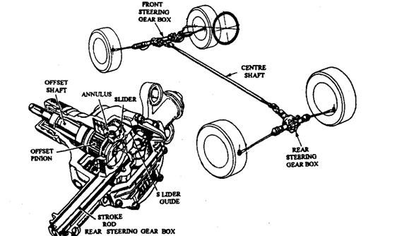
Fig. 27.77. Honda 4WS layout.
the reduction of body roll and cornering force on the tyre, improves the stability of the car so that control becomes easier and safer.
In a 4WS system, the control of drive angle at front and rear wheels is most essential. The Honda and Mazda systems vary in the manner their wheel angles are controlled. Honda system uses mechanical rear steering and the Mazda layout incorporates a rear gearbox, which is power-assisted as well as electronically controlled. Both systems have a power-assisted rack-and-pinion steering layout for the front steering gearbox with a take-off connection to control the rear steering gear box through a centre, or transfer, shaft. Two or more universal joints installed on the shaft allow the small variations in drive angle.
27.9.2.
Honda 4WS System
This system is dependent on the steer angle so that the movement of the rear wheels is controlled by the angular movement of the front wheels. For steering of the front wheels up to about 130 degrees, the rear wheels are so arranged that they turn through a small angle in the same direction as the front wheels. Beyond this angle, the rear wheels gradually straighten up and then turn through a comparatively large angle in the opposite direction (Fig. 27.76).
An epicyclic gear mechanism incorporated in the rear steering gearbox (Fig. 27.77) controls the rear wheels angles. A fixed annulus is meshed with a large planet gear, which is driven by an eccentric on the input shaft. A short shaft in integral with the planet and is offset from the centre of the planet. This shaft transmits a drive through a slider and guide to a stroke rod, connected to the rear wheel track rods (Fig. 27.78A).
Slight movement of the input shaft rotates the planet which in turn moves the offset output shaft slightly in the same direction as the input (Fig. 27.78B). As the input shaft moves the offset shaft towards the TDC position (Fig. 27.78C), the stroke rod rotates back to the central position so that the rear wheels are set in a straight ahead position.
As the input shaft and planet are rotated towards the full-lock position (Fig. 27.78D), the stroke rod attains maximum displacement and consequently a corresponding movement of the rear wheels takes place. The rear gearbox is maintenance free and is greased for its entire life. The centre shaft couplings have splines to both steering gearboxes. A master spline at each connected point ensures correct assembly of the units.
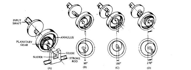
Fig. 27.78. Epicyclic gear action (Honda).
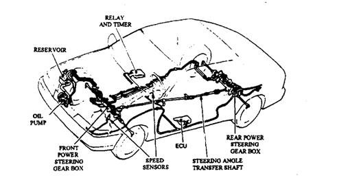
Fig. 27.79. Mazda 4WS layout.
27.9.3.
Mazda 4WS System
The rear wheels in this system are steered by a hydraulically operated power unit, which is electronically controlled in accordance with the steering wheel angle and vehicle speed (Fig. 27.79). The Mazda 4WS layout is more complicated than the Honda arrangement and hence incorporates suitable fail-safe for trouble free operation. The fail-safe device includes a centering lock spring and special safety solenoid. If hydraulic or electronic failure takes place, these devices set the rear wheels to the straight-ahead position.
Two electronic sensors, installed at transmission output and speedometer drive, measure the vehicle speed. The signals are passed to the built-in memory of an electronic control unit (ECU), which commands the hydraulic system for setting the direction and angle for the rear wheels. For speeds less than 35 kmph, the rear wheels are steered in the opposite direction to that of the front wheels. As 35 kmph is approached, the rear wheels are turned to the straight-ahead position. Above this speed the rear wheels are steered in the same direction as the front wheels with an angle limited to 5 degrees.
Figure 27.80 represents the schematic of the system and indicates the main components used in this system. The functions of these components in steering the rear wheels are as follows:
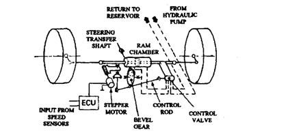
Fig. 27.80. Schematic layout of rear-wheel steer unit (Mazda).
(i) Sensors to measure vehicle speed.
(ii) Steering phase control unit conveys to the hydraulic control valve the required stroke direction of movement.
(Hi) Electric stepper motor alters the yoke angle and bevel gear phasing in accordance with the signals received from the ECU.
(iv) Rear steering shaft provides the position of the front wheels to the bevel gear in the steering phase control unit.
(v) Control valve controls the hydraulic pressure supplied to the ram cylinder.
(vi) Hydraulic ram cylinder steers the rear wheels depending upon the requirements.
The steeringphase control unit (Fig. 27.81) alters the direction and angle of the rear wheels. The electrical pulses from the ECU to the stepper motor, and the movement from the steering shaft to the bevel gear, alter the position of the hydraulic control valve to suit the conditions.
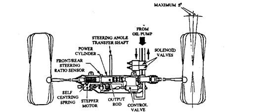
Fig. 27.81. Steering phase control unit.
