12.4.
Forced Circulation Water Cooling System
The water-cooling system (Figs. 12.6 and 12.8) has the major components such as water jackets, circulating pump, fan, thermostat, connecting pipes and hoses, radiator and radiator cap. The direction of cooling water flow is upward from the cylinder head to the top tank of the radiator, then downward through the radiator core to the bottom tank. From the bottom tank it moves through the lower radiator hose to the cylinder block water jackets and then through the water pump, which circulates the water. Water enters the engine at the centre of the inlet side of the pump. The circulating pump is driven by a belt from the crankshaft. As engine speed increases, the flow of coolant increases.

Fig. 12.6. Forced circulation water cooling system.
System Cooling Capacity.
The capacity of liquid cooling system is usually expressed as the quantity of coolant circulating through the system. The system cooling capacity can be obtained using the following relation.

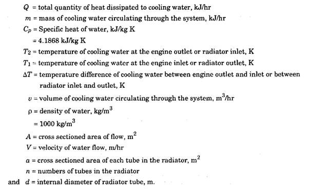
Example 12.1. The output from a car engine is 80 kW. The thermal efficiency of the engine is 25% and heat lost to the coolant is 30% of the heat supplied. How much heat should be dissipated from the radiator of the car ? The engine coolant (water) is to be cooled in the radiator from 353 K to 303 K. Estimate the quantity of water to be circulated for proper engine cooling. Cp of water is 4.183 kjlkg K.
![clip_image004[4] clip_image004[4]](http://lh6.ggpht.com/_Ii1ukGkfijY/SqoqpY8qqHI/AAAAAAAAC60/qf89PiTDvXg/clip_image0044_thumb.jpg?imgmax=800)
12.4.1.
Water Pumps
Usually centrifugal pump is used for the circulation of water in the cooling system. Figure 12.7 shows the construction of a centrifugal pump, which is driven by a fan belt mounted on a common shaft with the fan. The centrifugal pump is non-positive in action and does not build up high pressure. It simply consists of a casing inside which an impeller containing vanc-s is rotated. Water enters the inlet pipe from the bottom of the radiator and is directed by a passage to the centre of the impeller where it is caught by the rotating vanes. Due to centrifugal force the water is thrown out into the stationary casing. The kinetic energy imparted to water by the impeller is converted into pressure energy in the stationary casing so that a pressure difference is created between the inlet and outlet of the pump causing forced circulation of water in the system. Since the impeller is always submerged in the water, a seal is used to make a water tight joint where the impeller shaft passes through the casing.
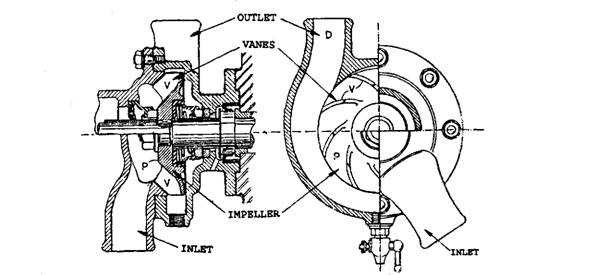
Fig. 12.7. Sectional view of a centrifugal pump.
The water pump on a V-8 engine at cruising speed pumps about 475 litres per minute of operation. Depending on the restriction of the thermostat and radiator, the water pump may create a slight positive pressure at the upper hose. The pump insures an adequate flow of coolant through the water jackets and radiator. The pump usually causes a flow of about 0.3 to 0.6 m/s through the radiator tubes. A slightly higher velocity although produces a greater efficiency in the radiator but causes a higher power loss at the water pump. Coolant flow with a velocity more than 1.8 m/s is considered a waste of power.
The water pump impeller shaft is supported by a double set of ball bearings which are permanently lubricated and sealed. A carbon seal is used to keep the coolant from leaking along the pump shaft. A weep hole in the housing allows any coolant that seeps past the seal to escape from the pump preventing corrosion or damage to the pump bearings.
12.4.2.
By-pass
The cooling system is provided with a bypass shown schematically in Fig. 12.8, which allows a small part of the coolant to circulate within the engine during warm up while the thermostat is closed. The by-pass is a small passage connecting the engine side of the thermostat to the inlet side of the coolant pump. The by-pass may be cast or drilled into the engine and pump parts, called an internal by-pass or may be visible as a hose on the front of many engines, called external by-pass, that connects the engine coolant outlet to the coolant pump. Coolant flows through the by-pass, short circulating the radiator when there is a pressure
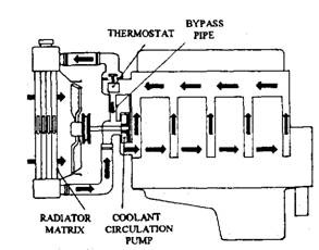
Fig. 12.8. By-pass system.
difference on the ends of the by-pass, even also the thermostat is open. The by-pass helps in uniform warm up, eliminates hot spots, and prevents excessive coolant pressure in the engine when the thermostat is closed.
12.4.3.
Drive Belts
Either the V-belt or serpentine belts system is now used to drive the water pump and other accessories. When more than one V-belt is used in the system, it is called as a poly-vee, or multi-vee belt. The V-belt system, shown in Fig. 12.9 A, may have two or more belts driving the engine accessories. The serpentine belt system, shown in Fig. 12.9B, is a single-belt system which drives all of the accessories.
The pitch and width of belts in the V-belt system are important, because they must match with the drive (engine crankshaft) and driven (engine accessories) pulleys. The belts are kept under proper tension to avoid slip and to provide proper grip between the belt and pulley V-belt^ use manual adjusting guide (Fig. 12.10) tension system. The serpentine belt system has’a spring-loaded belt tensioner. If the belt does not remain tight in this case, the tensioner has to be replaced.
It may be noted that the water pump pulley in Fig. 12.9A rotates in the opposite direction to the pump pulley in Fig. 12.9B. It is therefore possible that the same engine using these belting systems require different water pumps and fans.
12.4.4.
Radiator Hoses
Two hoses connect water jackets to the radiator. The upper hose transfers hot coolant to the radiator while the lower hose returns the coolant which is relatively cool. These hoses must be somewhat flexible to allow the engine to move on the mounts. Also hose flexibility allows slight misalignment between the outlets of the radiator and the engine. In addition it dampens engine vibration and protects the radiator.
Hoses are constructed around an inside tube of synthetic rubber. One or two layers of woven textile are placed around this inner tube. An outer layer of rubber is then placed around these textile piles. In order to have increased life of the hose, the rubber material used for construction should be oil and heat resistant. Silicone rubber materials are used for high heat conditions.
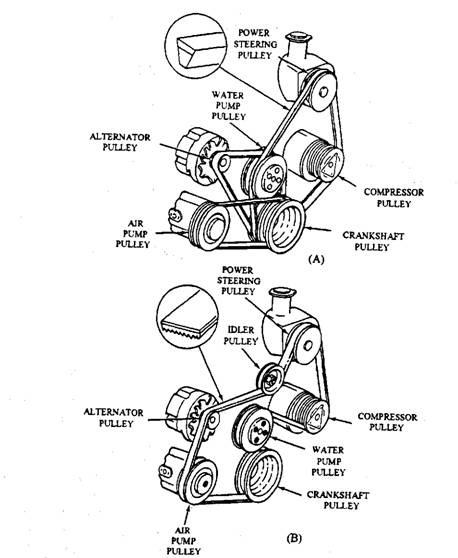
Fig. 12.9. Drive belts systems. A. V-belt arrangement. B. Serpentine belt arrangement.

Fig. 12.10. Method of adjusting V-belt tension.
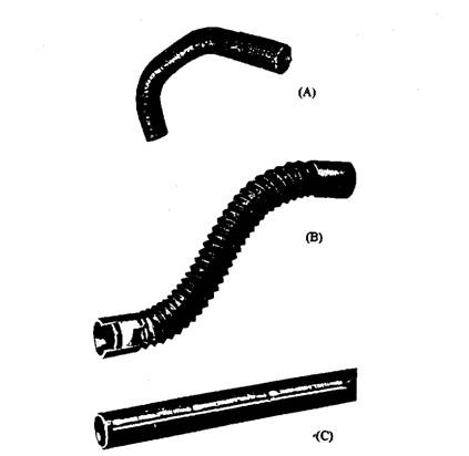
Fig. 12.11. Common radiator hoses. A. Curved. B. Flexible. C. Straight.
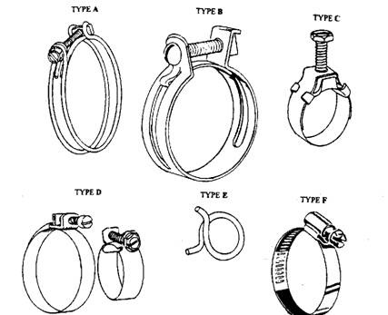
Fig. 12.12. Common hose clamps.
Lower radiator hose should have reinforcement of spring-like coils of wire to provide adequate strength from collapsing due to pump suction.
Radiator hoses are commonly available in three different forms (Fig. 12.11); straight (Fig. 12.11A), flexible (Fig. 12.1 IB), and curved (Fig. 12.11C). Several types of clamps (Figs. 12.12A through F) are available to make leak-proof joints for the coolant. The better clamps exert a high amount of clamping pressure evenly around the hose. Table 10.1 compares the major differences among six types of clamps (Fig. 12.12),
Table 12.1. Hose Clamp Characteristics.
| Type | Clamping Force | Force Distribution | Tendency to cut Hose | Ease of Installation |
| A | Good | Good | Does | Usually requires hose removal |
| B | Good | Fair | Can | Easy |
| C | Poor | Poor | Does not | Difficult |
| D | Weak | Fair | Does not | Difficult |
| E | Weak (when old) | Fair | Does not | Difficult (Requires special tool) |
| F | Very good | very good | Does not | Easy |
12.4.5.
Radiator
The radiator (Fig. 12.13) is a heat exchanger which transfers heat from the coolant to the air. An adequate flow of both coolant and air is required for proper exchange of heat. After the engine has warmed up, all of the additional heat absorbed in the water jackets must be dissipated at the radiator, otherwise coolant temperature increases. Evaporation of coolant takes place at a faster rate if the coolant temperature reaches boiling point, so that sufficient quantity of coolant is not available for heat transfer and consequently overheating of engine takes place.
Radiator Construction.
The radiator has a core, two tanks, some times an additional heat exchanger (cooler) for automatic transmissions, and the necessary mounting brackets. Exchange of heat occurs in the core, which consists of tubes that transfer coolant from one tank to the other and fins that transfer heat from the tubes to air. The exploded view of a radiator is shown in Fig. 12.14A and B. The radiator with a surge tank is shown in Fig. 12.14A and one with a transmission fluid cooler is shown in Fig. 12.14 B.
Radiators can be constructed with the tanks at the top and the bottom of the core or on the sides. If the tanks are at the top and bottom, it is a down-flow radiator (Fig. 12.13A) and the coolant flows from the top to the bottom. If the tanks are on the sides, it is a cross-flow radiator (Fig. 12.13B) and the coolant flows across the radiator from one tank to other. Theoretically, the down-flow radiator is more efficient. However if the radiator is wider than its height, efficiency is improved with a cross-flow design, as coolant travels in a longer path through the radiator. In this design the reserve tank is placed on the outlet side.
PRESSURE
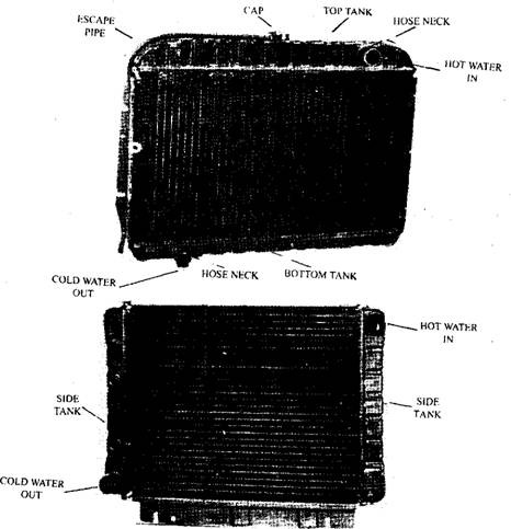
Fig. 12.13. The radiator. A. Down flow. B. Cross flow.
Radiators are designed to obtain the maximum rate of heat transfer using minimum material and size to keep the cost a low as possible. However, vehicle designs dictate available radiator space which affects radiator designs. Two types of radiator cores such as the serpentine fin core (Fig. 12.15A) and the plate fin core (Fig. 12.15B) are in common use in automobiles. The coolant flows, in each of these types, through oval shaped tubes and hence heat transfer takes place through the tube wall to fins, which are exposed to an air flow created by the fan for removal of heat.
The radiators are mostly made from yellow brass or copper which are corrosion resistant, have good heat transfer ability (better thermal conductivity), are easily formed, have required strength characteristics, and are easily repaired by soldering. Aluminium is used for radiators in special applications where weight is critical. Core tubes are made from 0.114 mm to 0.3 mm thick brass sheet, which are rolled into round tubes and the joints area sealed with a locking seam. The tubes are then coated with solder, compressed into an oval shape and cut to length. Fins are formed from 0.075 mm to 0.127 mm thick copper or brass sheet. Serpentine fins are formed from solder-coated sheet, stacked between the tubes, and held in a fixture. These assemblies are heated in an oven to fuse the joints and then the assembly is submerged in liquid
solder. Capillary action pulls solder into the joints, assuring a tight joint. The serpentine design is least expensive of the two types. Plate type cores are stronger than the serpentine cores, because plate type core is mechanically held by the fins as well as solder where as the serpentine type is held together by the soldered joint alone.
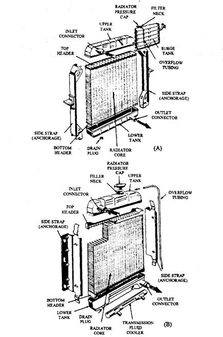
Fig. 12.14. Exploded view of a radiator.
A. Radiator incorporated with a surge tank. B. Radiator incorporated with a
transmission fluid cooler.
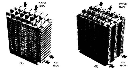
Fig. 12.15. The radiator cores. A. Serpentine core. B. Plate type core.
The tanks serve as a type of manifold that connect the tubes in the core to the radiator inlet or outlet connections. The radiator filler cap/pressure cap and overflow connections are usually built into one of the tanks. A few systems use a surge tank, and mount the filler neck and cap in the surge tank. The automatic transmission fluid cooler, if used, is placed in the radiator outlet tank. Traditionally, the tanks have been made of brass sheet of thickness 0.5 mm to 1.25 mm. The filler neck and the drain boss are of brass. Newer radiator designs use plastic tanks that are sealed to the header by an “O” ring or flat gasket and held in place by bending/crimping the header flanges.
The supporting sides are usually made of steel. Mounting straps to attach the radiator to the car body are soldered onto the tanks on some designs. Other designs do not use separate mounts, but the tanks are cradled in rubber brackets. Radiators with plastic tanks usually have mounting ears formed in the tanks.
Radiator Heat Transfer.
Heat transfer coefficient for air is about seven times less than for water and hence the air side limits heat transfer in a radiator. The heat transfer capacity of a radiator depends upon the number of fins for a given width, the radiator height, width and thickness, and the number of coolant tubes with a given frontal area. Radiator capacity can be increased by increasing the core thickness, packing more material into the same volume or both. The core must be capable of dissipating heat energy approximately equal to the power produced by the engine. As a thumb rule, 0.093 sqm of radiator core area is capable of cooling about 25 to 30 kW under normal conditions. Coolant tubes are straight and fins are often given a pattern to create turbulence by breaking any laminar air flow, but this increases resistance. Therefore care is taken while designing a radiator to provide maximum cooling with minimum air resistance. Dimples or louvers are often provided in the fin so that the air flow through the core becomes turbulent, thereby increasing air-to-fin contact and efficiency. Some newer corrugated fin designs can use
up to 7 to 9 fins per cm. If more than 4 fins per cm are used on vehicles, which are operated in dirty environments, then dust or dirt clogging the core may become a problem.
12.4.6.
Radiator Pressure Caps or Filler Caps
The hotter the radiator, the better is the heat transfer to the air. With water as the coolant, the highest temperature a radiator could operate at is 373 K, the boiling point of water. Addition of ethylene-glycol in a sealed radiator can substantially raise coolant pressure as well as boiling point.
The filler neck is fitted with a pressure cap to pressurise the cooling system to raise the boiling point of the coolant. The pressure cap incorporates a light relief valve with an automatic vacuum break valve. The relief valve is spring loaded to open at a pressure of 20 to 28 kPa above prevailing atmospheric pressure. One type of pressure cap is shown in Fig. 12.16.
The pressure inside the radiator is communicated through the central port to the pressure disc valve. The disc valve is loaded to a pressure of about 24 kPa whereas the vacuum valve to a pressure of about 7 kPa. The vacuum valve allows air to re-enter the system as the system cools, so that the radiator parts do not collapse under a vacuum. The spring disc does not leave its seating until the main body is well clear of the sealing washer and the pressure is reduced to that of the atmosphere, thereby guards against spurting on removal of the cap. The pressure cap is provided with an escape pipe.
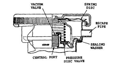
Fig. 12.16. Pressure cap or filler cap.
Excess pressure over that of the valve usually forces some coolant from the system through the escape pipe or overflow pipe leading out below the radiator and the coolant from the systems connect the overflow to a plastic container where excess coolant is held while the system is hot. When the system cools, the pressure is reduced and coolant is pulled back into the system. By increasing the boiling point of the coolant, the heat dissipating capacity of the radiator surface is increased appreciably. A higher loading of the relief valve can also give such a gain in temperature so that economy in size of radiator might be possible. However the necessity of strengthening the engine block to withstand higher pressure rules out any saving in radiator weight. Also the higher coolant temperature may cause pump cavitation.
Pressure caps should be removed from hot engines with caution. If the coolant temperature is above 373 K or even lower at altitudes above sea level, the coolant boils immediately if the pressure is released. Hence serious burns may occur if pressure caps are removed improperly. A safety step is provided on all filler necks, which prevents sudden removal of the pressure cap.
12.4.7.
Coolant Recovery Systems
Coolant recovery systems (CRS), which are used with most modern cooling systems, offer several advantages. Coolant that expands out of a system as it warms up is caught in a separate plastic container (Fig. 12.17). Water expands 0.18 percent for each one degree K increase in temperature. When the coolant cools down, a vacuum is created in the cooling system. The vacuum siphons some of the coolant back into the radiator from the expansion tank. The correct coolant level is provided between the marks on the coolant recovery container. The non-pressurized recovery tank has a capacity of about 1.8 land contains approximately 0.5 / of coolant when the cooling system is cooled.
The greatest benefit from coolant recover is that the radiator can be kept completely full. Lower coolant level in the radiator allows coolant to mix with air. Air travelling through the water jackets and radiator transfers lesser heat than the same volume of coolant. Air also promotes corrosion on the material. Thus a coolant recovery system improves efficiency and life of cooling system.
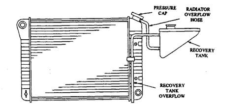
Fig. 12.17. Cooling system with a coolant recovery tank.
In a cooling system without CRS the coolant drips out through the overflow tube into the street. Therefore, coolant level is usually kept 20 to 35 mm below the filler neck on down-flow radiators and 50 to 100 mm below the filler neck on cross-flow radiators to allow for expansion of coolant. This minimises overflow of coolant in the system without CRS.
12.4.8.
Thermostats
The thermostat is used to control the minimum operating temperature of the engine, so that overcooling is prevented. A overcooled engine wastes fuel and wears out at an abnormally fast rate. Also, computerised ignition cars do not run in the normal operating mode until the coolant sensor is at normal operating temperature. A thermostat temperature-controlled valve is placed at the engine coolant outlet to restrict coolant flow until the engine reaches the operating temperature of the thermostat. When the thermostat is open (hot), coolant flows from the water jackets to the radiator and what it is cold, it stops the flow to or from the radiator (Fig. 12.18). On some engines, the thermostat is mounted at the water pump inlet (Fig. 12.19).
All thermostats operate in the same way and all thermostat designs use a by-pass passage (Fig. 12.18), so that coolant is circulated through the water jackets by the water pump to ensure an even and complete warm-up of the engine. Thermostats are designed to open at specific
temperatures, known as the rating of the thermostat, which may be stamped on it. The two frequently used ratings are 358 K and 364 K. Most thermostats begin to open at their rated temperature and they are fully opened at about 11 degree higher (i.e. at 375 K).
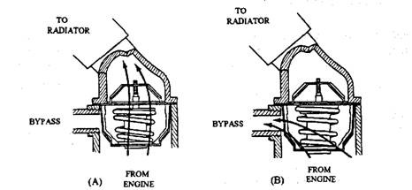
Fig. 12.18 Thermostat positions. A. Open. B. closed.
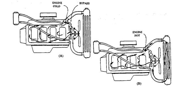
Fig. 12.19. Thermostatically controlled coolant flow. A. Thermostat closed. B. Thermostat open.
Several designs have been used over the evolution of thermostats. The alcohol bellows-type thermostat (Fig. 12.20) is an old version in which the heating of bellows evaporates liquid alcohol creating enough pressure to expand the bellows and the movement of the bellows operates the linkage so as to open the valve. This design has a tendency to operate erratically in pressurised systems and sometimes changes its opening because of differences in water pump pressure as the engine speed changes.
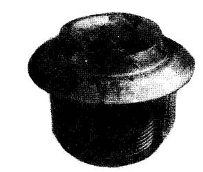
Fig. 12.20. A bellows type thermostat.
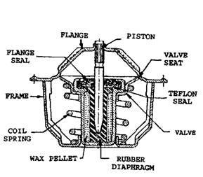
Fig. 12.21. Wax-pellet type thermostat.
The most widely used thermostat of the day is the wax-pellet type (Fig. 12.21). As the engine warms, heat swells an encapsulated wax-based plastic pellet located on the engine side of the thermostatic valve. This opens the thermostat through a mechanical link, which allows a portion of the coolant to flow to the radiator according to the engine cooling requirements needed to maintain normal temperature. The remaining portion of the coolant continues to flow through the by-pass. The coolant pump forces the coolant to flow. The thermostat restriction causes system pressure to rise, and the pressure lowers as the thermostat gradually opens, thereby increasing the coolant flow rate. Under extreme heating conditions of the engine like idling in traffic or moving up a long steep grade in hot weather, the thermostat opens wide allowing maximum coolant flow.
The pellet type thermostat is slightly more expensive than the bellows type. If failure occurs the valve remains closed in the pellet type but it remains open in the bellows type. Opening and closing temperatures can be accurately controlled in the pellet type. In addition they are relatively sensitive to variations of pressure in cooling system and they do not suffer from metal fatigue unlike the bellows type. If failure occurs while in the closed position severe engine overheating results. This may be noted by an extremely hot engine and a cool-to-warm radiator. If failure occurs while in the open position, a longer-than-normal warm up period may be noted by the cold dash lamp or temperature gauge.
A small air bleed hole is usually placed in the thermostat body or valve or a notch cut into the mounting flange of the thermostat. This bleed hole or notch allows air to escape from the water jackets as they are filled with coolant. Bleeding the air out helps insure that the cooling passages are completely filled during coolant changes.
12.4.9.
Fan and Fan Drives
The forward movement of the car at highway speeds insures an adequate flow of air, called ram air, through the radiator to carry off the heat and hence fans are not really needed at this
operating condition. A stopped or slow moving car generates more heat in the engine than the slow moving air can absorb, and as a consequence the engine overheats unless a fan is installed to provide enough air movement.
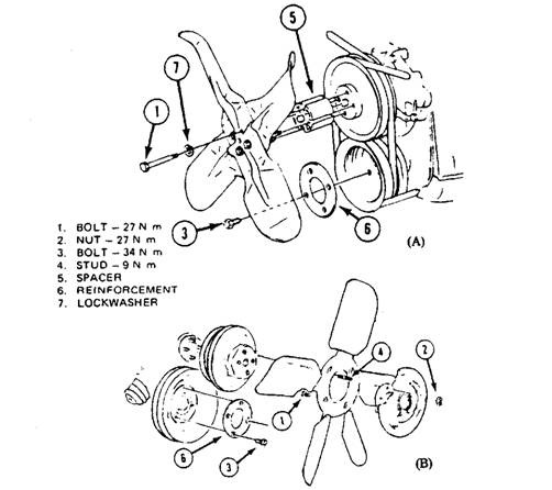
Fig. 12.22. Cooling fan. A. Without clutch. B. With clutch.
A cooling fan is installed, usually on the coolant pump shaft, for forced circulation of air across the radiator core. The fan is designed to provide its rated output at the lowest fan speed with the engine at its highest coolant temperature. There are several types of fans and fan drives in use. They are :
(i) Fixed-blade fan with direct drive.
(ii) Fixed-blade fan with clutch drive.
(Hi) Variable-blade/pitch fan with direct drive.
(iv) Fixed-blade fan with electric drive.
Out of the four categories, first three are commonly used. Figure 12.22A and B represent respectively fixed blade fan without and with fan clutch. The choice of fan type and size is usually determined by the air flow requirement of the car. The amount of air that a fan moves is determined by the fan diameter, the pitch of the blades (amount of blade angle/curvature), and the number of blades. The power required to drive the fan increases faster than the increase in
fan speed. Running a fan at speeds above 2000 to 2500 rpm is considered to be a waste of power/fuel, and it also contributes unwanted noise. The disadvantage of directly driving the fan through the water pump shaft is that it always runs at the same speed of the pump.
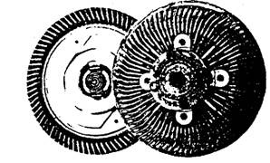
Fig. 12.23. Typical fan clutch.
Fan Clutches.
Fan clutches are often attached to the water pump shaft/drive pulley. The clutch is designed to slip at higher shaft speeds and, some times, at cool radiator temperatures. The clutch (Fig. 12.23) drives the fan through viscous drag of silicone fluid which transfers power from the input member (water pump shaft connected to clutch disc) to the output member (the clutch body with provision for mounting the fan and thermostatic valve with a reservoir, if used). The clutch body and disc often have annular
grooves that intersperse/mesh with each other (but do not touch) to increase their surface area and, therefore, their drag. The viscous fluid transfers enough power (0.37 to 1.84 kW, depending on clutch size, for passenger cars) to run the fan up to about 1000 to 2500 rpm and then slip at higher speeds.
A thermostatic fan clutch (most common type in latest cars) has the ability to run at low speeds when the engine is cold, higher speeds when the engine is hot, and still slip at higher speeds. Figure 12.24 illustrates the speed of a fan, for cars and light trucks, without a clutch (straight line) and the speed of a fan with the thermostatic clutch engaged and disengaged. The speed differential between the faster clutch disc and the slower body tends to pump the fluid outward. This fluid is then routed into the reservoir chamber. If the fluid leaves the clutch disc/annular groove area, very little power can be transmitted and the fan turns at very slow speeds. When the engine warms up, hot air causes a thermostatic coil or bimetallic spring to
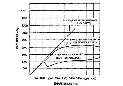
Fig. 12.24. Fan speed with and without clutch engaged.
change position and unmask a fill/return hole. The silicone fluid now returns to the drive area and the fan speed increases up to design speed.
Variable-pitch Fans.
Variable pitch fans (Fig. 12.25) draw low power with less noise at high speeds and provides high air volume at slow speed. The blades are made with a very large pitch from a flexible material, either stainless steel or fiberglass.
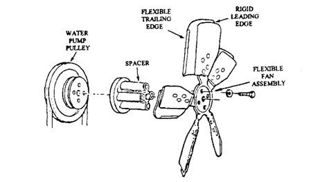
Fig. 12.25. Flexible fan details.
The flexible blades are attached to a strong, nonflexible centre section which is bolted to the water pump shaft. Because of the greater pitch, this fan moves a larger volume of air at slow speeds. At higher speeds, the flexible blades tend to flatten out, which reduces the pitch, air flow, power requirement, and noise level. These fans are available in different diameters and with a varying number of blades to provide the correct amount of air flow. Figure 12.26 illustrates air flow characteristics of three different types of fans.
Fan Shrouds.
The efficiency of a fan can be improved by installing a shroud surrounding the tips of the blades. A well designed shroud increases the air flow as much as 20 percent with a reduction in power required to drive the fan. A shroud reduces the amount of air, thrown from the tips and prevents the reverse flow (Fig. 12.27). An un-shrouded fan must be mounted close to the radiator (at a distance of 13 to 25 mm from the radiator), to insure an air flow through the radiator. This increases the possibility of the fan hitting the radiator and reduces air flow in the area of the fan’s centre and the corners of the radiator core. A well designed shrould permits the fan to be mounted any distance from the radiator. Also, it causes in a near equal air flow across all parts of the radiator core. The shroud should be designed to have about 20 mm gap between the inside of the shroud and the tips of the blades so that adequate clearance is available as the engine moves on its mounts. The fan should be located such that the front third to half of the fan is inside of the shroud.
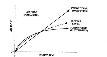
Fig. 12.26. Air flow characteristics of cooling fans.
A. Flexible blade fan (solid drive).
B. Fixed-pitch blade (solid drive).
C. Fixed-pitch blade (clutch drive).
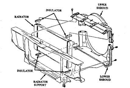
Fig. 12.27. A two-piece radiator shroud.
Electric Fans.
In many recent car models, to save power and reduce noise, the conventional belt-driven, water-pump-mounted engine coolant fan has been replaced with an electrically driven fan (Fig. 12.28). Electric fans offer several advantages such as, they can be mounted wherever they are needed, run at a constant speed, be turned of or on whenever needed, and do not draw power directly from the engine. The electric fan uses a fractional kW motor while the mechanical fan uses several kW motor. Normally electric fan motors are mounted on the radiator shroud.
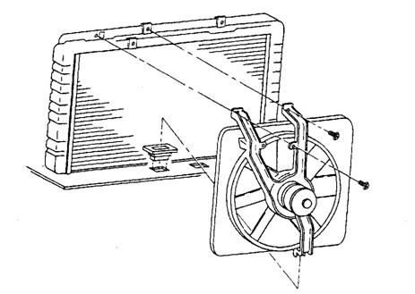
Fig. 12.28. Exploded view of electric cooling fan.
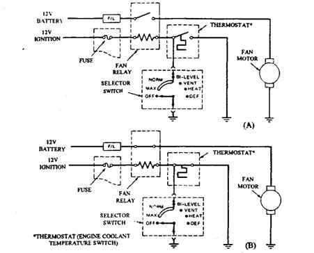
Fig. 12.29 Typical diagram for electrical fan-motor. A. Fan not operating. B. Fan operating.
The 12 V motor-driven fan is electrically controlled by either an engine coolant temperature switch (thermostat) or the air-conditioner select switch or both. Figure 12.29 illustrates the circuit diagram for the electric fan. The cooling fan motor is connected to the 12 V battery supply through normally open set of contacts in the cooling fan relay. Protection for this circuit is provided by a fusible link (F/L). During normal operation with air conditioner off the engine coolant below a preset temperature (normally 375 K), the relay contacts are open (Fig. 12.29A) and the fan-motor does not operate. When the engine coolant temperature exceeds 383 K, the engine coolant temperature switch closes (Fig. 12.29B), which energizes the fan relay coil and in turn closes the relay contacts. The ignition switch, however, should be in the on position.
