22.7.
Fluid Suspension
Figure 22.29 illustrates the basic principle of a hydro-pneumatic system, in which a liquid is used to transmit the force from the suspension piston to the gas in a closed container. The working of this system differs from the normal metal/spring suspension. In this case, the suspension unit is supported by a mass of nitrogen gas, which remains constant irrespective of the load carried by the wheel. When the load on the wheel increases, the volume of gas reduces so that gas pressure increases progressively causing stiffening of the suspension.

Fig. 22.29. Hydro-pneumatic suspension system.
22.7.1.
Hydragas Suspension
This system is basically the extension of the hydrolastic type of suspension, where the rubber spring is replaced by a pneumatic spring. Figure 22.30 illustrates the layout of one of the four hydragas units installed in a vehicle. A fluid pipeline links the front unit with the same side rear unit so they are interconnected in pairs. This line equalizes the liquid pressure in the two units so that the fore and aft pitching motion, most noticeable on short-wheel base cars, is reduced. The unit consists of mainly a nitrogen gas spring, a liquid displacer and a damper valve block.

Fig. 22.30. Hydragas suspension.
During upward movement of the wheel, suspension arm deflects the diaphragm and compresses the liquid. If the pressure in the other displacer unit is similar, then the liquid flows through the damper, so that the gas is compressed and the resistance to the suspension arm increases progressively. On rebound the liquid flows in the opposite direction. Energy, which causes the spring to oscillate, is absorbed as the liquid is passed through the damper. The action of the interconnecting liquid lines in relation to pitch, roll and bounce is similar to that in the hydrolastic system.
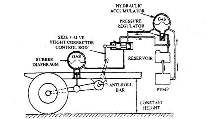
Fig. 22.31. Layout of hydro-pneumatic suspension system.
A hydraulic control unit in the hydragas suspension system permits the driver to adjust the ground clearance of the vehicle as well as maintains this clearance irrespective of the load carried.
The layout of a system similar to that used by Citroen is shown in Fig. 22.31. Each wheel is mounted on a suspension arm that is supported by pneumatic spring. Anti-roll bars are connected tranversely between the suspension arms at the front and rear, and are linked to height correctors by means of control rods. An engine-driven pump supplies oil under pressure to a hydraulic accumulator, which is connected to the height control or levelling valves.
The downward movement of the vehicle structure due to loading causes rotation of the anti-roll bar. This moves the slide valves to uncover the supply port so that oil flows from the accumulator to the suspension cylinders. When the vehicle reaches the desired height, which can be set by a selector inside the car, the anti-roll bar and control rod move the slide valve back to the neutral portion. As vehicle load decreases a similar sequence follows except that valve movement allows the oil to move from the suspension cylinder back to the accumulator.
A delay device or dash-pot is installed in the height corrector valve to prevent rapid flow of oil through the valve when the wheel encounters a bump or dip in the road. Without the dashpot, sudden movement of the wheel causes the valve to work continually, which provides an unsatisfactory operation.
Damping is provided by partially separating the oil in the spherical chamber from the cylinder in which the piston slides. A disc-type valve allows the oil to flow through small holes to and from cylinder and sphere in a way similar to other hydraulic dampers.
The hydraulic pressure in the Citroen system is also utilized for power assistance in steering, braking and gear changing. In one layout, a braking system with independent front and rear brake circuits is interconnected with the hydraulic suspension system. This system proportions the braking effort at each wheel as per the load it carries.
22.7.2. Air Suspensions for Commercial Vehicles
Figure 22.32 shows a rigid six-wheel truck fitted with pairs of air springs per axle. In the front suspension, the air springs are installed between the underside of each chassis side-member and the transverse axle beam. In the rear tandem suspension, the air springs are mounted between each trailing arm and the underside of the chassis (Figs. 22.33 and 22.34).
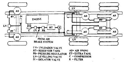
Fig. 22.32. Air spring suspension layout (plan view).
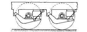
Fig. 22.33. Tandem trailing arm rolling diaphragm air sprung suspension.
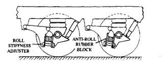
Fig. 22.34. Tandem trailing arm bellows spring suspension with rubber anti-roll blocks.
The engine compressor supplies air to the reservoir tank through the unloaded valve and the pressure regulator valve. Air also passes to the brake system reservoir (not shown). When the compressed air reaches pre-set upper limit, usually between 785 to 810 kPa, the unloaded valve releases any further air delivery from the compressor directly to the atmosphere. Once the air supply to the reservoir drops to a lower limit of 711 kPa, the unloaded valve then automatically closes its exhaust valve so that air is now delivered to the reservoir to replenish the air consumption. The level of air pressure required by the brakes is greater than that for the suspension system. Therefore, a pressure regulator valve is used between the unloader valve and suspension reservoir valve to reduce the delivery pressure to approximately 540 kPa required for the suspension.
Air now flows from the suspension reservoir to both the front and rear suspensions through a single central levelling valve at the front (Fig. 22.35) and a pair of levelling valves on each side of the first tandem axle. These levelling valves are actuated by an arm and link rod attached to the axles. The levelling valves sense any change in the chassis to axle height and then accordingly increase or decrease the air pressure supply to the air springs, thereby respectively raising or reducing the chassis height. The air pressure in the springs varies from 540 kPa at fully loaded condition to 245 kPa when the vehicle is empty.
To improve the quality of ride, volume of air in the system including air springs is increased by installing extra tanks. This minimizes fluctuations in overall pressure and reduces the spring rate.
An isolating valve, installed at the front end of the suspension, splits the air supply to the left and right hand air springs. This valve also allows compressed air to pass immediately to both air springs if there is a demand for more air and slows down the transfer of air from the outer spring to the inner spring when the vehicle body rolls.

Fig. 22.35. Air spring suspension layout (front view).
Levelling Valve.
The valve is pre-set with a time delay before air is allowed to flow to or from the air spring. This prevents the operation of the valve by axle bump or rebound movement as the vehicle encounters rough road surfaces, or by increased loads caused by the roll of the body on prolonged bends or on highly cambered roads.
The valve unit uses a hydraulic damper and the air control valve (Fig. 22.36A and B) and both are actuated by the horizontal operating lever fixed to the axle through a vertical link rod. When the operating lever is raised or lowered, the parallel leaf springs fixed to the lever casing pivot about the cam spindle that is mounted in the top of the assembly housing. The outwards deflection of both leaf springs applies a twisting movement to the came spindle, so that attached actuating arm is tilted. Accordingly the dash-pot piston moves either to the right or left against the fluid resistance. There is a small time delay before the fluid escapes from the compressed fluid side of the piston to the opposite side through the clearance between the piston and cylinder wall, after which the piston moves over progressively. A delay of 8 to 12 seconds on the adjustment of air pressure has been found suitable, making the levelling valve inoperative under normal road surface driving conditions.
When the laden weight increases the operating lever is swung upward (Fig. 22.36A), so that the piston moves to the right. This causes the tubular extension of the piston to close the exhaust valve and the exhaust valve stem to push open the inlet valve. Air then passes through the inlet valve to the respective air springs. Flow of air continues until the predetermined chassis-to-axle height is attained, at which point the lever arm swings down to move the piston to the left
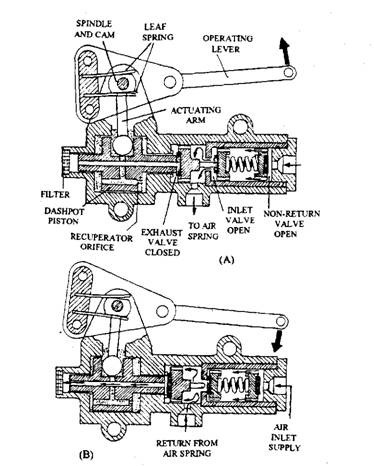
Fig. 22.36. Levelling air control valve. A. Air spring charging. B. Air spring discharging.
sufficiently to close the inlet valve. In the loading phase, the springs neither receive nor lose air and it is therefore the normal operating position for the levelling valve and springs.
When the vehicle is partially unloaded (Fig. 22.36B), the chassis rises relative to the axle causing the operating arm to tilt downward, so that the piston moves to the left. Consequently the exhaust valve opens and excess air escapes through the centre of the piston to the atmosphere until the correct vehicle height has been established. Now the operating lever begins to move the piston in the opposite direction, closing the exhaust valve. A non-return valve on the inlet side prevents air loss from the spring until maximum loading occurs or if the air supplies form the reservoir fails. This cycle of operation is repeated when the vehicle’s laden weight changes.
Isolating Valve.
During cornering of the vehicle air is pumped from the spring under compression to that under expansion, which can considerably reduce the resistance to body roll. This problem is prevented by an isolating valve, which contains T-piece pipe air supply junction with a central cylinder and plunger valve (Fig. 22.37A and B).

<A> Fig. 22.37. Isolator valve. (B)
A. Air spring charging position. B. Anti-roll air cross flow restriction position.
During changing of the air spring, compressed air enters the inlet part of the valve from the levelling valve and pushes the shuttle valve towards the end of its stroke (Fig. 23.37A). Air passes through the centre of the valve and comes out radially through the annular groove around the valve, which aligns with the left and right hand output ports, connected by pipe to the air springs.
When the levelling valve stops the air supply to the air springs, the shuttle valve seals both left and right hand outlet ports (Fig. 22.37B) preventing the highly prssurized outer spring from transferring its air charge to the expanded inner spring, which is subjected to much lower pressure under body roll conditions. The shuttle valve is a loose fit in its cylinder to permit a slow leakage of air from one spring to the other when one spring is inflated more rapidly than the other, due possibly to uneven loading of the vehicle.
Air Spring Bags.
Air spring bags generally consist of the two or three convoluted bellows (Fig. 22.38) or rolling lobe (diaphragm) type (Fig. 22.39), each having distinct characteristics. Usually, the bellows air spring (Fig. 22.38) is a compact flexible air container and can be loaded to relatively high pressures. Its effective cross-sectional area changes with spring height, which increases and decreases respectively with the increase and decrease of the static height. To accommodate large variations in static spring height, the three convolute bellows types is necessary, but for
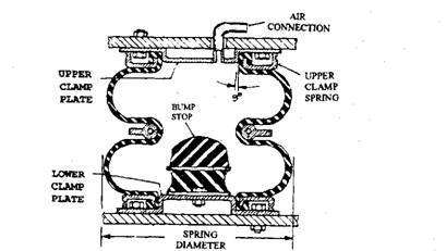
Fig. 22.38. Involute bellow spring.
moderate suspension deflection the twin convolute bellow is sufficient for expansion and contraction demand. The rolling diaphragm or lobe spring (Fig. 22.39) requires a relatively higher installation space at lower static pressures. Progressive spring stiffening is achieved by tapering the skirt of the base member to increase the effective working cross-sectional area of the rolling lobe as the spring approaches its maximum bump position.
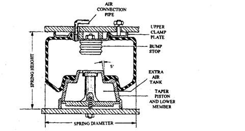
Fig. 22.39. Rolling diaphragm spring.
The springs are made from tough Neoprene rubber reinforced with nylon for application at low and normal operating temperature, but Butyl rubber is occasionaly preferred for high operating temperature requirements. An air spring bag is consisted of a flexible cylindrical wall made from reinforced rubber enclosed by rigid metal end-members. The shape of external wall of the air spring bag may be either plain or bellow type. The flexible wall normally uses two or more layers of rubber coated rayon or having nylon cord laid in a cross-ply fashion with an outside of abrasion-resistant rubber. Sometimes an additional internal layer of impermeable rubber is provided to minimize the loss of air.
The bellow type air spring bags (Fig. 22.38) are positioned by an upper and lower clamp ring, which wedges their rubber-moulded edges against the clamp plate tapered spigots. The rolling lobe bag (Fig. 22.39) is located upon the necks of the spring fitting tightly over the tapered and recessed rigid end members. Both types of spring bags have flat annular upper and lower regions for producing and self-sealing action, when exposed to the compressed air.
The bellows spring has a natural spring frequency range of 90 to 150 cycles per minute (cpm) for a simply supported mass when fully laden and acting in the direct mode, and the rolling lobe type has 60—90 cpm. The higher natural frequency for the bellow spring is due mainly to the more rigid construction of the convolute spring walls, as compared to the easily collapsible rolling lobe. A rubber limit stop of the progressive type is installed inside each air spring as a precaution against the failure of the supply of air pressure for the springs. Compression of the rubber begins when a bump causes about 50 mm travel of the suspension.
