17.11.
Exhaust Gas Recirculation
Exhaust gas recirculation (EGR) is an emission control system, which reduces the amount of oxides of nitrogen (NOx) produced during combustion. Since peak combustion chamber temperature is dependent on ignition timing, the spark timing control systems discussed in section 17.10 were the first attempts to meet NOx control requirements. Exhaust gas recirculation systems were designed as a better method to control NOx than the spark timing controls. Small amounts of NOx are formed at temperatures below 1645 K, and these quantities can be easily controlled. But once combustion chamber temperatures become 1645 K or higher, more NOx is formed. As indicated above, the peak combustion chamber temperatures can be lowered by two ways to prevent NOx formation. One is to retard spark timing slightly. The more efficient method is to dilute the incoming air-fuel mixture with a small amount of inert gas.
Since exhaust gases are relatively inert, they are used to dilute the air-fuel mixture in the cylinder to lower the combustion chamber temperature. Small quantities of exhaust gas (6 to 10 percent) from the engine’s exhaust ports are routed to the intake manifold (Fig. 17.57). Since exhaust gas contains no oxygen, the resulting air-fuel-exhaust gas mixture does not produce as much heat when ignited as an undiluted air-fuel mixture produces.
The amount of NOx produced at low engine speeds is very small, hence exhaust recirculation is not desirable at idle. Also it is undesirable

Fig. 17.57. Basic exhaust gas recirculation methods.
during high-speed driving at wide-open throttle, to achieve efficient operation and good driveability. Maximum recirculation is required during cruising and acceleration at speeds between 48 to 112 kmph, when NOx formation is highest. At low engine temperature, NOx formation is also low, and hence recirculation is avoided to produce fast warm-up and better driveability.
17.11.1.
System Components and Operating Principles
The device used to re-circulate exhaust gas is presented in the following pages. Each manufacturer has adopted some variation of the basic system, to achieve exhaust gas re-circulation. Various temperature sensors, flow valves, and other control devices used in the EGR system modulate the flow of exhaust gas to maintain driveability while reducing NOx emissions.
EGR Floor Jets.
The floor jet system (Fig. 17.58), the simplest among all EGR system, is used on some 1972-73 Chrysler-built engines. The stainless steel jet provides an opening between the exhaust passage and the intake manifold. On V-8 engines, the jet is fixed to the floor of the intake manifold under the carburettor. With 6-cylinder engines, the jet is in the intake manifold hot spot beneath the carburettor. The manifold vacuum controls the flow of exhaust gas into the intake system through the jet orifice. However, in this system the exhaust gas flows into the intake manifold at all times. This is a major drawback, which causes rough engine operation at idle and during cold engine warm-up.
EGR Valves.
The EGR valve (Fig. 17.59) was first installed on 1972 Buicks and is a spring loaded, vacuum operated, poppet-type valve, which meters the exhaust gas entering the intake system. Modulating valves and tapered-stem valves are also used as EGR valve and their operation is almost the same as the poppet type. The EGR valve is installed on the intake manifold (Fig. 17.60) or on a spacer in between the carburettor and the intake manifold (Fig. 17.61). The valve is connected to the intake and exhaust systems either by internal passages in the intake manifold (Figs. 17.60 and 17.62) or in some cases by external steel tubing. The spring holds the EGR valve in the closed position. The valve is opened by ported or venturi vacuum from the carburettor.

Fig. 17.58. Chrysler’s floor jet EGR system.

Fig. 17.59. Typical EGR valve.
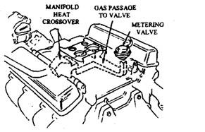
Fig. 17.60. EGR metering valve mounted on intake manifold.
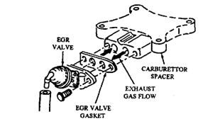
Fig. 17.61. EGR valve mounted on a plate under the carburettor.
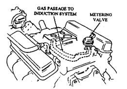
Fig. 17.62. Exhaust gas passages to the EGR valve.
Ported Vacuum Systems.
The ported vacuum controlled EGR systems have a slot-type port in the carburettor throttle body above the throttle plate (Fig. 17.63), and the port is connected to the EGR valve by a vacuum line. When the throttle plate is closed, the vacuum is
not transmitted. Opening of the throttle plate exposes the port to the manifold vacuum. The exhaust gas flow depends on manifold vacuum, throttle position, and exhaust gas back pressure. As ported vacuum can at the maximum be equal to intake manifold vacuum, re-circulation at wide-open throttle is prevented. The valve opens at a point greater than the relatively weak manifold vacuum produced during wide-open throttle operation.
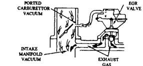
Fig. 17.63. EGR valve is operated by ported vacuum.
Venturi Vacuum Systems.
The venturi vacuum controlled EGR systems have a vacuum port at the throat of the carburettor venturi to provide a control vacuum (Fig. 17.64). This control vacuum is very weak, so a vacuum amplifier boosts it sufficiently to operate the EGR valve. Although the exhaust gas flow depends mainly on engine intake airflow, it is also affected by intake vacuum and exhaust gas back pressure.
A relief valve or dump diaphragm compares venturi and manifold vacuum and prevents re-circulation of exhaust gas at wide-open throttle. When the. diaphragm senses the throttle at wide open, the stored vacuum in the amplifier is released to the atmosphere. This prevents the manifold vacuum to reach the EGR valve. Since the EGR valve opens at a point greater than the relatively weak manifold vacuum, the valve remains closed at wide-open throttle.
Vacuum Amplifiers.
The vacuum amplifier (Fig. 17.65) boosts the weak venturi control vacuum so that it is strong enough to operate the EGR valve. To achieve this manifold vacuum is stored in a reservoir inside the amplifier unit. This maintains higher vacuum level irrespective
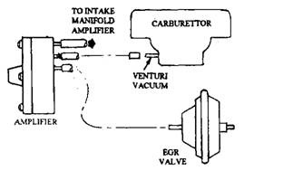
Fig. 17.64. EGR systems controlled by venturi vacuum.
of the variations in manifold vacuum. Whenever the venturi vacuum is equal to, or greater than, manifold vacuum, a relief valve or dump diaphragm vents the reservoir, cancelling the output EGR signal.
The vacuum amplifier can produce in ideal condition an accurate, repeatable, and almost precise proportion between venturi airflow and EGR flow. However, vacuum amplifiers are not common on late-model EGR systems because storage reservoirs generally have the problem of leakage during use.
Back-pressure Transducers.
This transducer is basically a diaphragm-operated sensor unit (Fig. 17.66) and uses a tube, which extends into an exhaust gas passage. When the tube senses a high exhaust back – pressure, the diaphragm closes an air bleed hole in the EGR vacuum line so that maximum EGR is provided during acceleration when back-pressure is high. As back-pressure drops, a spring moves the sensor diaphragm to reopen the vacuum line so that the vacuum at the EGR valve is decreased, causing a reduction in the circulation of exhaust gas.
Modulating Devices. Various methods of modulating, or adjusting, EGR valve operation in relation to engine operating conditions have been developed. High and low ambient temperature vacuum modulators are used to weaken the vacuum signal to the EGR valve. A coolant temperature override switch or valve (Fig. 17.67) sometimes eliminates EGR vacuum below certain engine operating temperatures. Some venturi-vacuum-controlled systems incorporates a time delay solenoid to shut off vacuum supply to the EGR valve for about half a minute once the ignition is turned on.
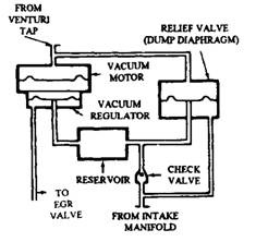
Fig. 17.65. Vacuum amplifier.
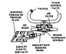
Fig. 17.66. Typical EGR back pressure transducer.
A vacuum-bias valve bleeds off part of the EGR vacuum signal under high-manifold-vacuum conditions to eliminate high speed surge. Also a dual-diaphragm EGR valve (Fig. 17.68) sometimes does this job. The valve uses manifold vacuum to enable the valve spring to offset the carburettor vacuum under certain cruising conditions.
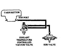
Fig. 17.67. Coolant temperature controlled vacuum valve.
