Electrical and Electronic Principles, and Automobile Batteries
The battery is considered as the most important component of the automobile electrical system, since it serves as the reserve source of electricity to operate whole of the electrical equipment. Even after well over 100 years of development and much promising research into other techniques of energy storage, the lead-acid battery is still the best choice for automobile use. This is particularly so when cost and energy density are of prime consideration. This type of secondary (reversible in charge/discharge) battery has lead plates immersed in an electrolyte (a liquid solution) of sulphuric acid and distilled water. The various types of lead-acid batteries include conventional, low maintenance and maintenance free.
The chapter mainly deals with conventional type of lead-acid batteries, and other two types are discussed in brief at the end. The types of batteries other than lead-acid are discussed in the chapter “Electrical and Alternate Fuelled Vehicles.” This chapter starts with a brief presentation of electrical and electronic principles, and basic electrical circuits in order to provide knowledge for easy understanding of the operation of all electrical and electronic systems incorporated in automobiles.
13.1.
Electrical and Electronic Principles
13.1.1.
Atoms and Electricity
All material in the universe is made of tiny particles called atoms. Every atom contains a compact and relatively heavy nucleus carrying a positive charge and about which orbit small negatively charged electrons. The nucleus itself is composed of two types of elementary particles called neutrons and protons. Each of the neutrons and protons has a mass of about 1.7 x 10″ 24 g, which is nearly 2000 times greater than that of the electron. Neutrons and protons are almost identical, but protons carry a positive charge and neutrons carry no charge. They both contribute for the mass of the atom. All protons are identical and carry the same amount of positive charge. All electrons are identical and carry the same amount of negative charge. The negative charge of electron is of equal magnitude but opposite polarity to the positive charge of the proton.
In the normal condition,, the number of protons in the nucleus of an atom is same as the electrons outside the nucleus,thereby balancing positive and negative charges. The atom, in this
condition, is said to be electrically neutral. If one of the orbiting electrons is made free from the atom, there is an excess of positive charge in the atom. The atom then is called as a positive ion. Conversely, if the free electron is attached to a (neutral) atom, then the atom has an excess of negative charge and is called a negative ion. The existence of free electrons causes the phenomenon of electricity.
13.1.2.
Insulators, Conductors, and Semiconductors
The process of removing electrons from atoms in any material is called ionization, which often requires lot of input energy, usually in the form of heat or a strong electric field. Materials having very few free electrons are difficult to ionize as they do not readily allow electric charge to pass within them. These materials are termed insulators.
In normal circumstances a negligible amount of electricity flows through an insulator. Eventually most of them break down and ionize under a sufficiently high voltage, allowing current to flow in the form of a spark. Most of the non-metals are good insulators. However, plastics and ceramics are the main insulating materials used in automobile electronics.
Conductors are materials in which atoms are surrounded by many free electrons and they normally exist in an ionized state. Most metals belong to this group of materials, which conduct electricity. Silver has the maximum free electrons than any metal and so is the best conductor of electricity. A cable is a length of flexible conductor, which transports electrons from one point to another. An appropriate insulating layer (usually plastic) is used to surround the conductor, so that escaping of electrons at the working voltage is prevented. An insulation that is adequate for a vehicle’s 12 V circuits would break down if used at the high voltages encountered in spark-plug leads. Copper being almost as good as silver and being much cheaper is generally used to make cables.
Between insulators and conductors, there exists a group of materials in which ionization occurs to a small extent at room temperature. These materials are known as semi-conductors, which conduct electricity much better than insulators, but not like conductors. As temperature is raised, semiconductors tend to conduct electricity better, releasing more free electrons through temperature induced ionization. Semiconductor materials are very important to the electronics industry being the raw materials for the manufacture of devices like transistors and diodes. Silicon is the best known of the semiconductors.
13.1.3.
Voltage, Current, and Resistance
In a metal like copper, each atom has a heavy nucleus containing 29 protons and 34 neutrons. They occupy a fixed position in space and from a stable lattice structure. The outer electrons of each atom are very weakly bound to their nucleus, enabling them to easily break free and ‘wander’ from atom to atom. This wandering motion is normally random, having no over all direction. However, through the application of an external force to these free electrons, all the electrons can be made to flow in the same direction. This flow of electrons is called the current (I), and the force that causes the current is called the electromotive force (emf). A generator or a battery supplies the emf, the strength of which is measured in units of volts (V). In conductors, a relatively small emf can produce a large current, whereas in insulators a very large emf is required to produce even a very tiny current.
A conductor of certain length if connected across the terminals of a source of emf, such as a battery, a chemical reaction within the battery takes place, which produces an excess of positive ions on one terminal and an excess of negative ions on the other. The negatively charged free
electrons in the conductor are attracted to the positive ions at the battery’s positive terminal so that they drift towards it, eventually entering the battery. These drifted free electrons in the conductor are constantly replenished by the excess of electrons at the negative terminal of the battery. Thus the battery’s emf causes an electrical current, which is measured in units of
amperes (A). A current of 1 A corresponds to 6.25 x 10 electrons passing a point in the conductor each second. This enormous number of electrons produces an amount of charge called a coulomb (C). An ampere is therefore defined as a rate of flow of charge of one coulomb per second. Electrons cannot be created or destroyed they can only be moved or redistributed to other parts of the electrical system.
The amount of current that can be produced on a conductor by the emf depends on the conductor’s electrical resistance (R), which can be considered as opposition to electron flow. The resistance gives rise to a voltage difference (more correctly, a potential difference) between two points along a conductor. Resistance is caused because drifting electrons occasionally collide with lattice atoms and release some of their energy so that the lattice atoms vibrate. This increase in atomic vibration is observed as additional heat in the conductor. Since the atoms in a hot conductor have a greater extent of vibration, they tend to be struck by more drifting electrons and so it is observed that the resistance of a conductor rises with its temperature.
Ohm’s Law.
In 1826 a German mathematics teacher, Gorge Ohm, made an important observation about the relationship between the current in a conductor and the voltage across it, that they are linearly proportional. Therefore, the resistance of a conductor is defined as the ratio VII, where Vis the potential difference across the conductor and/ is the current in it. In other words, voltage (volts) divided by current (amps) equals resistance (ohms). Mathematically, VII = R (which can also be written as V = IR or / = V/R). This important mathematical relationship is known as Ohm’s Law and is widely used in electrical engineering. It states that the current in a conductor increases in direct proportion to the applied voltage, with resistance being the constant of proportionality. One ohm (1 Q) is the resistance of a conductor through which a current of one ampere (1 A) flows when a potential difference of one volt (1 V) is maintained across it.
Ohm’s Law suggests that electrical conductors (wires, cables and so on) must be properly sized to carry the required current without having significant resistance. This means, higher the current and, to some extent the longer the distance of flow of current, thicker the conductors have to be. A too thin conductor offers too much resistance to the current it carries and the voltage at the exit from the conductor is much less than at the entrance, causing a voltage drop along the conductor.
Resistors.
Since a good conductor like copper has very less resistance, a specially made electronic component, called a resistor, is used when there is a need to increase the resistance in a circuit. Most resistors used in electronic circuits are made of either a rod of powdered carbon or a very thin layer of metal. Copper connecting leads are attached to the resistor body and the whole assembly is coated with an insulating material. Resistors are available with fixed values, from a fraction of an ohm to about a million ohms. They are also available to have adjustable values determined by a rotating shaft or slider. This type of resistor is usually known as variable resistor or potentiometer.
Measurements of Current, Voltage and Resistance.
Most often measurement of current, voltage and resistance are required in electrical systems.
Current in a component is measured with an ammeter by connecting it in series with the component. It is important that the ammeter should have very small resistance, so that it does not restrict the flow of current in the circuit.
Voltage is measured with a voltmeter. Since voltage is the difference in potential between two points in a circuit, a voltmeter is connected across the ends of the components whose voltage is to be measured. For measuring voltage, it is necessary that the voltmeter must have a very high resistance, so that it draws no current.
An ohmmeter measures the resistance of a component. It applies a voltage to a component, measures the ensuring current, and displays the result in ohms. Ohmmeters can give accurate result only if the component under measurement is disconnected from the rest of the circuit.
Nowadays, a single instrument is available called a digital multi-meter (DMM), in which an ammeter, voltmeter and ohmmeter are incorporated. A DMM has a digital display and uses push buttons or rotary switches to select the type of measurement required i.e. volts, amps or ohms. Numerous models of DMM are found and some of these are specifically designed for automobile use.
The oscilloscope is one of the most versatile instruments for electrical measurement. This can display a rapidly changing voltage, in graphical form, on the face of a cathode ray tube (CRT) like a small TV tube. These are very useful of examining fast changing signals such as the voltages applied to fuel injectors or spark plugs. Specially designed sophisticated oscilloscopes for use on automotive electronic systems, are now available. These oscilloscopes are usually linked to a microcomputer system, forming a part of a complete engine analysis/diagnosis system.
13.1.4.
Electrical Circuits
An electrical circuit is a conducting path around which electrons can flow. The path starts and ends at the source of the emf, such as the automobile battery. Between the battery terminals the circuit may be subdivided into branches involving many components. Generally the circuit path is closed (i.e. unbroken) so that a current flows. When the circuit path is opened {i.e. interrupted), the flow of current ceases. An open circuit may be due to the action of a switch or fuse or be the result of a poor connection. The current may also find a shortcut route around some of the components in the circuit, known as a short circuit, in which the current is much greater than intended. Short circuits normally arise through a fault condition; for example an unintended connection or the failure of insulation.

Fig. 13.1. Common circuit symbols used in automobiles.
Circuit Diagrams.
Circuit diagrams are drawn to understand the operation of a perticular circuit. A circuit diagram can be considered as a kind of ‘map’ of the electrical system, which indicates all the possible routes that the current can take and with small pictorial symbols shows all the different components in the system including their interconnections between each other. Although there is considerable variation in the use of electrical symbols between different motor vehicle manufacturers, some common circuit symbols generally used are illustrated in Fig. 13.1.
While drawing circuit diagrams, it is always the convention to use that the current flows from positive to negative, i.e. opposite to the direction of electron flow. This rule arose because early scientists had wrongly considered that current was due to tiny positive charges flowing from the positive terminal of a battery and returning to the negative terminal. The error was realized only in 1917 after the discovery of the electron. As it was too late to change the rule, the same convention is still in use when working with circuits. Although use of this conventional current is technically incorrect, it rarely causes problem.
In a circuit diagram for a metal bodied vehicle, the body shell is almost always connected to the battery’s negative terminal. This helps to use the body shell as the return conductor for the circuit, which considerably simplifies the wiring, thereby reduces the cost, weight and complexity of the electrical system. Electrical systems on a car are thus invariably connected between the battery positive terminal and the body (the ‘earth’ or ‘ground’ connection).
13.1.5.
Series and Parallel Circuits
A vehicle’s electrical circuits consists of a number of components connected between the vehicle’s battery terminals constituting a circuit. Components in the circuit can be connected in series (end-to-end in a ‘string’), so that same current flows in each (Fig. 13.2), or can be arranged in parallel so that the current divides between them (Fig. 13.3).
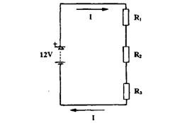
Fig. 13.2. Resistors connected in series.

Fig. 13.3. Resistors connected in parallel.
Series Connection.
Figure 13.2 represents three resistors connected in series, and hence all carry the same current /. The potential difference developed across each of the resistors may be calculated using Ohm’s Law.

Thus in a series circuit:
(i) The current is the same through all resistors.
(ii) The total potential difference is equal to the sum of all the individual potential differences.
(Hi) The individual potential differences are directly proportional to the individual resistances.
(iv) The total resistance is larger than the largest individual resistance.
(v) The total resistance is the sum of the individual resistances. Parallel Connection.
Figure 13.3 shows three resistors connected in parallel. Voltage, Vt is applied to all of the resistors. The current, It, divides into I\, 1% and I3 through the three resistor branches.
![clip_image002[6] clip_image002[6]](http://lh5.ggpht.com/_Ii1ukGkfijY/Sqn57aU6pZI/AAAAAAAACyg/9Bjz8yy4OOc/clip_image0026_thumb.jpg?imgmax=800)
Thus in a parallel circuit:
(i) The potential difference is the same across each resistor.
(ii) The total current in the circuit is the sum of the individual branch currents.
(Hi) The individual branch currents are inversely proportional to the individual resistances.
(iv) The equivalent resistance of the circuit is smaller than the smallest individual resistance.
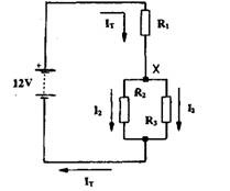
Fig. 13.4. Series parallel connected resistors.
Series-parallel Circuit.
A series-parallel circuit is a combination of both series and parallel current paths. Figure 13.4 shows a simple series-parallel resistor circuit. The circuit current (It) passes through the resistor Ri, but divides at the point X, where it flows through the resistors R2 and Rz in inverse proportion to their values. In order to perform calculations on series-parallel circuits it is first necessary to replace the parallel components with their single-resistor equivalent value, Req, and then proceed as for a series circuit.
![clip_image006[4] clip_image006[4]](http://lh4.ggpht.com/_Ii1ukGkfijY/Sqn5-z-bcZI/AAAAAAAACyw/yQOxC9dolUA/clip_image0064_thumb.jpg?imgmax=800)
The Potential Divider.
The potential divider circuit (also called a voltage divider) is very useful in electronics and most electronic systems use potential divider. Figure 13.5A represents the arrangement of the potential divider having two resistors connected in series. The current in the circuit, /, is calculated using Ohm’s Law,
![]()
Thus the potential divider shown in Fig. 13.5A provides a fixed fraction, V% of the input voltage Vjn-

Fig. 13.5. Potential divider. A. Simple two-resistor divider. B. The potentiometer.
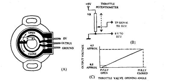
Fig. 13.6. Sensing throttle position using a potentiometer.
A. Construction of the throttle potentiometer (Mazda).
B. Circuit connection.
C. Output signal according to throttle valve opening.
In place of fixed resistors described above, a long resistive track with a sliding contact (Fig. 13.5B), called a wiper, can give a continuously variable potential difference. These resistive tracks, known as potentiometers, (in short form called as ‘pots’) are widely used in electronics. The wiper may be either straight, to give linear adjustment, or curved to give a rotary adjustment over an angle of 100-200 degrees. In automobile electrons the potentiometers
indicate the angular position of a shaft. A rotary potentiometer (Fig. 13.6A) is used to sense the position of a throttle shaft. Figure 13.6B shows the circuit connection of the potentiometer. When the throttle is closed, and the engine at idle, the wiper is at a position close to the 0 V terminal, so that the output voltage sent to the engine management electronic control unit (ECU) is very small (approximately 0.5 V). As the throttle is opened the shaft rotates, so that the wiper is moved along the resistive track toward the supply voltage terminal of the potentiometer thereby increasing the output voltage sent to the engine management system. At wide open throttle (WOT), the output voltage nearly equals the supply voltage, indicating about 4.3 V. The output voltage from the potentiometer thus serves as an indication of throttle opening, and hence the power demands on the engine (Fig. 13.6C).
Wheatstone Bridge.
Circuits with two potential dividers are known as bridge circuits, used frequently in measurement systems. The Wheatstone bridge (Fig. 13.7A) is the most common type of bridge circuit. A constant input voltage, Vm, is applied to the two potential divider pairs, with resistors R\,R3 and R2, r4. The voltages Va and Vb, at terminals A and B respectively, are equal if the ratios of Ri : R3 and R2 : i?4 are the same. A voltmeter connected between the two terminals does not indicate any potential difference so that the bridge is balanced. When one of the resistor values is changed slightly, the two potential dividers do not provide exactly the same output voltage. The voltmeter now shows a small potential difference, in proportion to the imbalance of bridge.
The bridge circuit is most commonly used for temperature sensing in automobile electrons. Figure 13.7B represents a bridge circuit in which the resistor R% has been swapped for a thermistor, whose resistance is highly temperature dependent. As the thermistor temperature increases, its resistance falls due to which the potential difference between point B and battery negative increases. The resistor ratio R\: R3 does not vary, so the voltage at point A remains constant. A voltmeter connected between A and B thus shows a voltage reading that increase with temperature.

Fig. 13.7. The Wheatstone bridge. A. Simple bridge circuit. B. Using a bridge circuit to monitor temperature.
13.1.6.
Electrical Energy and Power
Electrons, in an electrical circuit, gain electrical energy from a battery or generator, the source of electromotive force and dissipate it into other forms like heat, light, and mechanical energy in various circuit components. They cannot be created or destroyed and so electricity are not ‘consumed’ in the components. Electrons simply act as a medium for the transfer of energy from one place to another.
Power is an indication of the rate of conversion of energy from one form to another. Since the converted energy (W) is measured in joules (J) and time is measured in seconds, the power is measured in joules per second (J/s) or watts (W) where, 1 watt (W) = 1 joule per second (J/s). The electrical power (P) delivered to , or consumed by, a component is determined in terms of the current in the component and the voltage across it, by using the equation, P = IV. Thus, watts equals the product of amps and volts (W = TV).
In an automobile electrical system it is important to know the electrical power needs of the components. As an example of a power calculation, consider a 12 V headlight bulb uses a 4.5 A current. The power of the bulb is, P = 12 V x 4.5 A = 54 W. This means, the bulb filament is changing 54 joules of electrical energy into heat and light energy each second. Since the automobile battery is supplying the electrical energy, it must therefore convert 54 joules of chemical energy into electrical energy each second.
Electrical Heating.
When current flows in a resistance, the total amount of dissipated electrical energy is converted into heat energy. By using Ohm’s Law (V = IR), the rate of generation of heat is given
as P = IV = IIR = I2 R. Thus, knowing the resistance and current in a circuit, the rate of production of heat in the components can be calculated. Also, a doubling of current produces a four-fold rise in heat production. This is why large current produce significant heating, even in conductors of very low resistance. The ‘square-law’ of heat production is applied for the vehicle
fuses. A fuse is an electrical safety device consisting of a short length of resistance wire that heats-up and melts if the current passing through it exceeds a limit. This limit is about twice the maximum safe continuous current, i.e. when the rate of heat production in the fuse wire is about four times the safe continuous maximum.
13.1.7.
Direct Current and Alternating Current
In a direct current (DC) circuit, the electrons flow steadily in only one direction. All the circuits discussed so far have been DC circuits. Batteries produce only DC, and therefore, to reverse the direction of the current in a battery-powered DC circuit, it is necessary to practically reverse the battery connections.
In an alternating current (AC) circuit, the electrons first flow in one direction for a short time and then reverse and flow in the opposite direction. Thus in AC circuits the direction of electron flow alternate on a regular basis.
Frequency and Period of an AC Waveform.
A waveform is a graphical plot, which indicates the variation of a current or voltage with time. Figure 13.8 illustrates the waveform for direct and alternat-
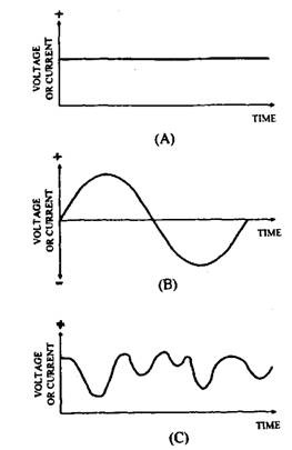
Fig. 13.8. Types of waveforms.
A. DC signal. B. AC signal.
C. Varying DC signal.
ing currents. The AC waveform shown in Fig. 13.8B represents mathematically the simplest kind of current alternation. This wave form is called a sinusoidal (or sine) wave in which the current starts from zero, rises to a positive peak value, declines again to a negative peak value through zero and then rises back to zero. This pattern of current alternation, called a cycle, is repeated again and again to give a continuous waveform. The number of cycles completed in a second is known as the frequency of the waveform.
The frequency (f) of the AC is measured in units of hertz (Hz). One hertz is one cycle per second (1 Hz = 1 c/s). The time taken for completing each individual cycle of the AC waveform is known as the period (jT) of the waveform. Period (T) and frequency (f) have a simple relationship, T = Vfand sof= 1/T.
Voltage and Current Values.
The voltage and current magnitudes of an AC waveform can be expressed in a variety of ways, the most important of which are the instantaneous, peak, peak-to-peak and rms values of the waveform (Fig. 13.9).
The instantaneous value of the waveform is the value of voltage or current at a particular instant of time. Instantaneous values are positive on the positive part of the waveform and negative on the negative part.
The peak value of the waveform (also called the amplitude of the waveform) is the value of the volt-
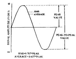
Fig. 13.9. Instantaneous, peak, peak-to-peak, rms and average values of an AC sine wave.
age or current, measured from zero to either the positive or negative peak and are denoted as Vp or Ip.
The peak-to-peak value of the waveform is the voltage or current, measured from the positive peak to the negative peak and is denoted as Vpp or Ipp. For example, AC mains are 240 V peak-to-peaks. For a sine wave, the peak-to-peak value of voltage or current is always twice the peak value.
The rms (root mean square) value of a waveform is mathematically determined. The rms value for a sine wave is a measure of the heating effect of the AC in a resistor. It is defined as that value of voltage (or current) equal to the DC voltage (or current), which produces the same amount of heating. Peak values for a sine wave can easily be converted into rms values by using the mathematical relations.
![]()
13.1.8.
Magnetism and Electromagnetism
It was only during the early nineteenth century a relationship between electricity and magnetism was discovered. This relationship is extremely important for automobile electronic systems since many components on a vehicle like solenoids, relays, ignition coils, and sensors rely on electromagnetic effects. Additionally, the interaction of vehicle electrical components with each other and with the external electromagnetic environment (electromagnetic compatibility or EMC) is also of considerable significance for automobile electronics.
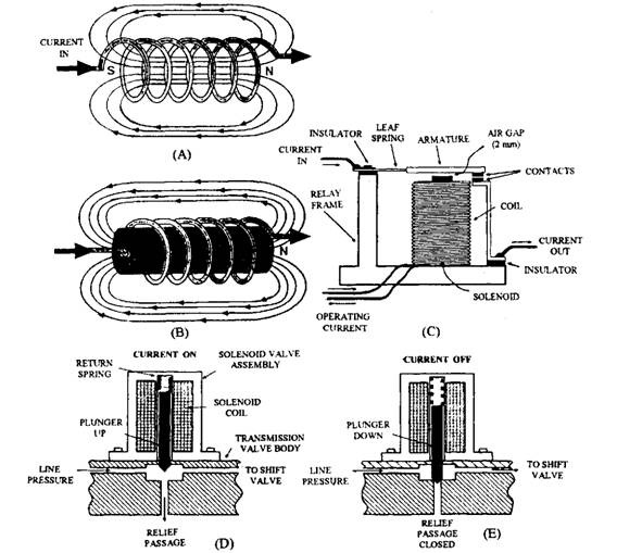
Fig. 13.11. Application of electromagnetism.
A. Simple solenoid.
B. Increasing the field with a core.
C. Construction of a simple relay.
D. and E Operation of a plunger solenoid valve in automatic transmissions.
13.1.9.
Applications of Electromagnetism
Electromagnetism finds a large number of applications in automobile ; the most common ones are the relay and the plunger solenoid.
Relay.
Relays enable a small control current to switch a much larger current in a relatively cheaper way, such as a motor supply, in a separate external circuit. Figure 13.11C illustrates a typical relay design. The relay is consisted of an iron-cored electromagnet, and mounted on an iron frame. The iron-core is wound with many turns of thin wire. The switching of the relay is carried
Magnetic Fields.
A magnet produces magnetic field, which is a region around itself, and in which a magnetic force is experienced. Some materials, once magnetized, retains their magnetism and hence are known as permanent magnets. Alnico retains its magnetism extremely well and hence is often used to make the permanent magnets for application in small motors. It has a composition of 54% iron, 18% nickel, 12% cobalt, 6% copper and 10% aluminium.
The presence of the field around a magnet can be observed by covering the magnet with a sheet of paper and scattering iron fillings onto it. Lines of flux emerge from the North Pole and re-enter the magnet at the South Pole. These lines indicate the direction of the magnetic force and the density of lines represents the concentration of the magnetism around the magnet. Since the direction of the magnetic force is opposite at the north and south poles, it is observed that when two magnets are brought close together the like magnetic poles repel and the unlike magnetic poles attract.
Magnetic Effects of Current.
The relationship between electricity and magnetism was observed first in 1820 by the Danish scientist Hans Oersted. He found that a compass needle deflects if it is brought close to a wire carrying a current. Oersted’s observation can be verified by scattering iron filing on a piece of card with a wire passing through it. When the wire carries a sufficiently large current, a magnetic field pattern of concentric circles are observed. When viewed along the wire in the direction of conventional current, it is seen that the field lines circle the wire in a clockwise direction, as in Fig. 13.10. This is known as Maxwell’s corkscrew rule, i.e. imagine driving a corkscrew in the direction of the current, the corkscrew would rotate clockwise.
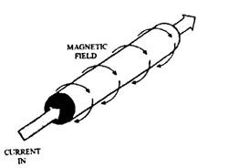
Fig. 13.10. Magnetic field due to a current through a wire.
Solenoid.
If a length of wire is wound to form a long cylindrical coil in which current flows, then the lines of magnetic force associated with each turn of wire add together producing a strong magnetic field within the coil, with north and south poles at each end, as shown in Fig. 13.11A. A solenoid is a coil, capable of producing a strong magnetic field and the field pattern is very similar to that of a bar magnet. Addition of a core material inside the coil (Fig. 13.1 IB) increases the density of the magnetic flux making it a stronger magnet. Core materials, such as glass, wood and plastic have a negligible effect on the flux density. Materials like iron, steel or cobalt greatly increase the flux density. By increasing the field strength with a core an electromagnet is produced. This magnet exhibits all the properties of a permanent magnet but if the current is withdrawn its magnetism suddenly disappears.
The flux density of an electromagnet is proportional (within limits) to the number of turns of wire in a specific length of the coil and the current in the coil. Therefore, a compact and powerful electromagnet can be made by using many turns of thin wires, however if care is not taken the resistance of the wire may limit the flow of current in the device.
out by a pair of heavy-duty contacts, one of which is fixed and the other attached to the moving armature. When operating current is not applied, a strong spring keeps the contacts apart so that no current is there in the external circuit. With the operating current (typically 50-100 mA) is applied, the armature is pulled down so that the contacts close, thus completing the external circuit.
In electronic language relays are relatively slow in switching and or unreliable devices. They are only suitable for use in undemanding control circuits such as switching for lights, motors, heaters, etc. Typically the operation time i.e. the time taken for the contacts to close is about 20 ms and the release time i.e. the time needed for the contacts to open is about 10 ms. Power semiconductor devices are very fast acting with high reliability.
Plunger Solenoid.
These solenoids are available in many shapes and sizes, and their internal design is usually the same. They are used in various automotive applications like the engagement of the pinion gear on pre-engaged starter motors, the control of fluid flow in fuel injection systems, automatic transmissions, anti-lock braking systems, and remote boot release actuators.
Figure 13.1 ID and E shows a simple automatic transmission fluid pressure control solenoid. The solenoid uses a coil of fine copper wire wound around a thin-walled cylindrical former. The fluid control needle (the plunger) works with a smooth sliding fit in the cylinder. With no supply of current to the coil, the plunger is held rigidly against the pressure relief port by the return spring. When current flows in the coil, the plunger is pulled into the cylinder against spring pressure so that fluid flows into the relief passage, reducing the fluid pressure within the system.
Therefore, variable control of fluid pressure is possible through this device by continually pulsing the solenoid ON and OFF in rapid alternation. This technique is knc* n as pulse width modulation (PWM) or duty cycle control. The principle of PWM is illustrated in Fig. 13.12. A high-speed electronic switch alternately turns the solenoid current ON and OFF. As the ratio of the ON time (T0n) to the OFF time (T0ff) is varied, the effective current supplied to the solenoid is also varied so that precise control of the solenoid position (to within a few per cent of its total travel) is possible. Such PWM control is common in fluid pressure and engine idle air control (LAC) valve applications.
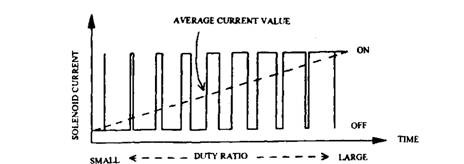
Fig. 13.12. Use of pulse width modulation to vary the average current through a solenoid. Motor Action.
Motor action is the motion resulting from the forces of magnetic fields. This can occur between the magnetic field associated with the current in a wire and a separate external
magnetic field. To obtain maximum force the conductor must lie in a direction perpendicular to the magnetic field, as illustrated in Fig. 13.13.
The force on the wire is proportional to,
(i) the length of wire, L, in the magnetic field.
(ii) the current, /, carried by the wire.
(Hi) the strength, B, of the magnetic field. Therefore, Force = BIL.
If a loop of wire is placed in the magnetic field then opposite sides of the loop have opposite current directions (Fig. 13.13). Thus the associated magnetic field is opposite and the force on each side of the loop is in opposite directions. One side of the loop is forced upward and the other downward, so that the loop has a resultant rotational force called a torque. All electric motors work on the principle of this torque.
Electromagnetic Induction.
While Oersted discovered the magnetic effect associated with electrical current, the British scientist, Michael Faraday succeeded in producing a current from a magnetic field in 1831. By moving a magnet through a coil of wire, Faraday could measure a voltage across the ends of the
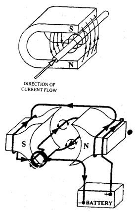
Fig. 13.13. Principle of motor action.
wire, which he termed as an induced emf. When the ends of the coil were connected, forming a closed circuit, Faraday found an induced current in the circuit caused by the induced emf. This discovery is responsible for the construction of electrical machines like power-station generators and automobile alternators.
Generation of Induced Current. Faraday further realized that a change in the magnetic field was only responsible for the induced current, so that only the relative movement between the coil and the magnet matters, and not the component, which actually moves. The induced current is the result of motor action between the external magnetic field and the magnetic field of the free electrons in the wire. In the absence the external magnetic field the free electrons have random movement without particular direction, and hence have no net field. When an external field is moved past the wire, motor action between the two sets of magnetic fields pushes the free electrons along the wire so that a current is observed.
When a length of wire is moved through a magnetic field, the induced emf increases with the increase of
(i) the speed of movement of the wire, V;
(ii) the length of wire, L in the field; and (Hi) the strength of the field, B.
The induced emf can be expressed mathematically by an equation very similar to force on the wire, as, Eind = BLV.
To make an electrical generator, a loop of wire can be rotated in a magnetic field. The induced emf is then available at the ends of the loop. This is simply the converse of the motor represented in Fig. 10.13.
13.1.10.
Inductance and Capacitance Inductance and Inductive Reactance.
Coils are the electrical components called inductors and when there is current in it a magnetic field is produced. As the current in the inductor rises or falls, the magnetic field respectively expands or contracts.
The change in current through the coil causes the magnetic field to change, which induces a voltage that opposes the original change in current. Inductors thus allow direct currents to flow, but oppose alternating (or varying DC) currents.
Inductance (L) is a measure of a coil’s ability to generate an opposing induced voltage, as a result of a change in its current. The unit of inductance is the Henry (H). Inductive reactance (Xl) is the resistance offered to a current by an inductor and is measured in ohms. Inductive reactance increases with the increase of the frequency, f, of the AC, and the inductance, L.
Energy Storage in an Inductor.
An inductor is used in automobile electronics to store energy and is the basis of most spark ignition systems. In an inductor the energy is stored in the magnetic field established by the current. The stored energy, E, can be calculated from the coil’s inductance and the current as,
E = LI 12, when L is in henrys and / is in amps, the E is in joules.
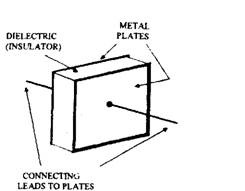
Fig. 13.14. Construction of a simple capacitor.
When the current through a coil is suddenly blocked,the magnetic field around the coil rapidly collapses. The magnetic energy, E, is then quickly liberated in the windings of the coil due to which a high voltage is produced. In petrol vehicles the ignition coil’s inductance and operating current are appropriately selected so that voltages in the order of 10000-40000 V are generated, which produce sparks at the spark plugs to ignite the air-fuel mixture.
Capacitance.
A capacitor is an electronic component, which can store a small amount of electrical charge. Capacitance (C) is the measure of a capacitor’s ability to store charge. A capacitor in its simplest form contains two parallel conducting plates
separated by a layer of insulating material, such as paper or mica, called the dielectric (Fig. 13.14). The plates are fixed with connecting leads and the device is encapsulated in a protective coating.
Charging and Discharging a Capacitor.
If a capacitor is connected to a voltage a charge accumulates on the plates, causing in an increase in potential difference across the plates. When the capacitor voltage equals the applied voltage, no more current flows onto the capacitor and the capacitor remains in the charged condition, whether or not the applied voltage remains connected. The capacitor discharges when if finds a current between the plates. It serves as a momentary voltage source, providing
a discharge current, until the voltage falls to zero. A simple circuit shown in Fig. 13.15 illustrates capacitor action. When the capacitor is connected to the battery, initially a large charge current flows, which falls as the voltage across the capacitor approaches the battery voltage. Thus, initially the bulb glows bright, which becomes dimmer and eventually goes out when the capacitor is fully charged. When the switch is moved to the discharge position, a large discharge current is initially present so that the bulb glows brightly for a moment, and fades as the charge flows off the plates.
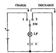
Fig. 13.15. Changing and discharging a capacitor.
Charge and Energy Storage.
The unit of capacitance is farads (F). One farad is a large amount of capacitance. Most capacitors have much smaller values ranging from a few nanofarads (nF or 10″ 9 F) to a few microfarads (uP or 10″ 6 F). The amount of charge, Q, stored by a capacitor, C, when charged to a voltage, V, is given by, Q – CV. Therefore capacitance, C = Q/V. Thus a one farad capacitor stores one coulomb of charge when one volt is applied across its plates.
The amount of energy stored by a capacitor is, W – (QV)/2, which is very tiny compared with that of a battery. However, this energy is still sufficient for use in applications like capacitor-discharge ignition (CDI) systems.
Capacitor-resistor Time Constant.
When the capacitor in Fig. 13.15 is connected to the battery, the current in the circuit does not remain constant because of the change in the bulb brightness. In reality, the charge current and the capacitor voltage follow the curves as shown in Fig. 13.16. The curves indicate that the
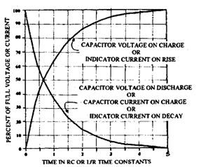
Fig. 13.16. Exponential curves associated with capacitor-resistor and inductor-resistor circuits.
charging current, Ic, has initially a maximum value when the battery is first connected, and then slowly falls as the capacitor becomes charged until it is zero. The capacitor voltage, Vc, rises very rapidly first, then slowly approaches the battery voltage as the capacitor is fully charged.
Curves of this shape, called the exponential curves, are characteristic of all capacitor-resistor (CR) circuits. The time constant for the CR circuit is the time, t, in seconds taken for the voltage or current to reach 63% of its final value (i.e. for the capacitor to reach 63% charge or discharge) and is calculated as, t = CR. To completely charge or discharge, a capacitor takes about five time constants (5 t).
CR circuits find several applications in electrons to provide a simple timing function, for example in wiper delay or courtesy-light delay applications.
Capacitive Reactance.
The capacitive reactance, illustrated in Fig. 13.17, is property of capacitors. The bulb lights briefly in Fig. 13.17A as the switch is closed because there is a charging current. Since the capacitor is fully charged after a short time, and no more DC flows due to which the bulb goes out. The capacitor is thus said to block direct current. In Fig. 13.17B the bulb continuously glows and hence it appears that the capacitor passes alternating current. Practically no current passes between the capacitor plates, but the electrons are able to flow on and off the plates in
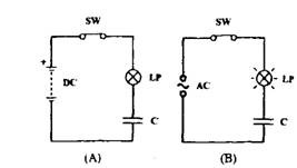
Fig. 13.17. Capacitive reactance.
A. The capacitor blocks DC.
B. The capacitor passes AC.
sympathy with alternating voltage of the supply, providing an alternating current through the bulb.
The opposition offered by a capacitor to a current is called its capacitive reactance (Xc). Capacitive reactance reduces as the capacitance is increased and also the frequency of the AC is raised. Additionally capacitive reactance is infinite for DC. In electronic circuits, capacitors are often used to ‘block’ the unwanted DC component of a signal or to filter-out an unwanted AC component (by shorting it to ground).
13.1.11.
Semiconductors
Semiconductors are materials that have a electrical resistance higher than conductors, but a much less than insulators. The electrical properties of semiconductors are strongly dependent on light and temperature, and this characteristic is much useful.
Among all types of semiconductor available, silicon is the most important one for the electronics industry, because it is easy to work with, abundantly available and very cheap. It also possesses ideal electrical properties for the manufacture of diodes, transistors, integrated circuits (ICs) and various types of sensors.
Conduction in Semiconductors.
At low temperatures there are very few free electrons available in semiconductors unlike conductors to conduct current so that electrical resistance is high. As temperature is raised, ionization occurs (electrons break free from atoms) in semiconductor, thereby increasing in the number of free electrons for conduction (hence the resistance falls) and forming an equal number of positive ions.
When a voltage is applied across a semiconductor, the negatively-charged free electrons tend to drift from the negative contact toward the positive contact, increasing the number of fixed positive ions at that end. Therefore, at the negative contact there are only few electrons and many positive fixed ions left. Although it is only the electrons that actually move, electron drift to the positive contact appears to be balanced by a drift of positive charge towards the negative contact. To account for this apparent positive charge flow, the concept of a positively-charged particle called a hole was invented. The hole has a charge of equal magnitude, but opposite polarity, to that of the electron and appears to drift through the semiconductor, same as the electron.
Intrinsic and Extrinsic Semiconductors.
A very pure semiconductor material is known as intrinsic semiconductor in which the number of free electrons is exactly balanced by the number of holes and the resistance of the material is relatively high.
Extrinsic semiconductor has as lower resistance and is manufactured by adding a tiny amount of impurity to intrinsic semiconductor so that there is an over-abundance of either holes or electrons.
This process of adding impurities to intrinsic semiconductor is called doping, which forms the basis for the production of useful devices, such as diodes and transistors.
N-type and P-type Semiconductors.
A semiconductor that has been doped for an excess of free electrons is called an n-type semiconductor (‘n’ stands for negative charge). Although there are still many positively-charged holes available in an n-type semiconductor, but they are very less compared to the free electrons and hence act as minority carriers. Therefore, conduction in n-type material is mainly due to electrons flow.
A semiconductor that has been doped for an excess of holes is called a p-type semiconductor Op’ stands for positive charge). In p-type semiconductor material conduction is mainly due to” holes flow, and electrons act as minority carriers.
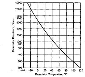
Fig. 13.18. Temperature response of an ntc thermistor.
13.1.12.
Semiconductor Devices
Semiconductor materials are used to manufacture some of the most useful electronic devices. The range of components now available is enormous, and those, important to the automotive industry, are described below.
Thermistors.
The thermistor (thermal resistor) is one of the simplest applications of semiconductor materials. Thermistors exhibit a resistance, which is strongly temperature dependent, unlike normal resistors that maintain a constant resistance almost independently of temperature. Thermistors are cheap and durable, so they are commonly used for various temperature sensing purposes on the automobile like engine coolant temperature, intake air temperature, exhaust gas temperature, etc. These thermis-
tors are generally of the negative temperature coefficient (ntc) type, so that their resistance decreases with increasing temperature. Figure 13.18 represents response of a typical ntc thermistor, which has the resistance of about 30 kQ at 293 K that falls steeply to about 180 £> at 373 K. An electronic control unit (ECU) senses the resistance value and interprets as a temperature for further processing or display. The temperature-resistance response is highly non-linear, and the ECU linearises change in thermistor resistance. Figure 13.19 shows a typical application of an engine intake air temperature sensor system. The ntc type thermistors are made from the powdered oxides of metal such as nickel, cobalt and manganese, formed into small pellets and fitted into a threaded holder complete with connector.
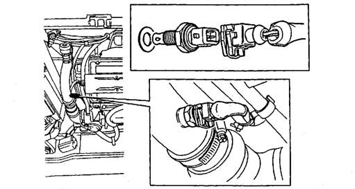
Fig. 13.19. An ntc thermistor used to measure engine intake air temperature.
The positive temperature coefficient (ptc) type thermistor has a resistance that increases with increasing temperature and is made from barium titanate. The ptc thermistors are less common and a typical application is the control of electrical heaters where a large current needs to flow at low temperature, which is progressively reduced as temperature rises. The ptc device can also protect the stalled electrical motor from excessive currents where, resistive heating in a series-connected ptc thermistor causes a sharp resistance rise, limiting the motor stall current.
Hall Effect.
E.H. Hall in 1879 detected a small voltage between the sides of a conductor when it was carrying current in a magnetic field. In metal conductors this voltage is tiny, but in semiconductors particularly indium arsenides (InAs) much larger voltages can be generated. The semiconductor material is particularly effective for this.
Figure 13.20 illustrates the principle of the Hall effect. The strong magnetic field deflects electrons flowing through the Hall ‘chip’ so that they tend to be bunched-up at one side, causing an excess negative charge. At the other side there
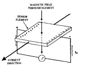
Fig. 13.20. Principle of Hall effect.
is an excess positive charge due to a deficiency of electrons. This difference in potential, called the Hall voltage, Vh, increases and decreases accordingly in proportion to the strength of the magnetic field, and is zero when there is no magnetic field. In general, a modest magnetic field with a current of about 100 mA, produces a Hall voltage of about 50 mV.
Hall sensors are cheap and rugged. The presence or absence of magnetism can be detected by using the Hall effect. This is widely used as a means of measuring shaft rotation in automotive electrons. Figure 13.21 illustrates an application of a Hall sensor as a trigger for an electronic
ignition system in place of contact-breaker points. The trigger system uses a rotor made of soft iron, with four vanes located at 90 degrees intervals at the outside edge. A pick-up fixed to the distributor base-plate, is a sensor containing a Hall device and permanent magnet for detecting the presence or absence of the vanes.
The rotor is fixed to the distributor shaft so that as it turns the vanes pass between the Hall element and the magnet. Absence of the vane between the sensor and the magnet allows the flux from the magnet to pass through the Hall device so that an output voltage is generated. Presence of the vane between the Hall element and the magnet obstructs the flux from the magnet to reach the sensor. The output from the sensor is thus a series of voltage pulses corresponding .
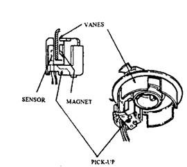
Fig. 13.21. Hall-effect pick-up used in a distributor.
to 90 degrees of crankshaft rotation. The ignition system ECU processes and amplifies these pulses for use.
The pn-junction.
One of the uses of semiconductors is in having a junction between layers of p-type and n-type material. The simplest junction device is the diode, constructed by putting a piece of p-type material in contact with a piece of n-type material. The diodes only allows current to pass through in one direction (the forward direction) and blocks the current in the reverse direction. The diode is, thus, a one way valve for electric current.
Figure 13.22 illustrates the circuit symbol and electrical characteristics of the silicon diode. When a forward-bias voltage of more than about 0.7 V is applied across the diode the forward current rises very steeply in a non-ohmic manner (i.e. the diode does not obey Ohm’s Law). When a reverse-bias voltage is applied to the diode it offers a very high resistance allowing only a minute leakage current. If a very high reverse voltage is applied, the diode may suddenly fail (or destroy itself) and allow a high reverse current to flow.
Types of Diode.
Although all diodes perform as electrical one-way valves, but they can be manufactured to exhibit additional useful properties.
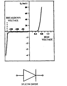
Fig. 13.22. Characteristics and symbol of the silicon diode.
Power Rectifier Diodes. These diodes are used to convert AC into DC, which is known as rectification. Figure 13.23 represents a simple rectifier circuit. The diode allows current only on the positive portion of the sine-wave and blocks current on the negative part. The current in the load is thus in one direction only. Rectifier diodes are used in all alternators, and are physically quite large as they are required to pass large currents.
Zener Diodes. If the reverse voltage of a specified value is applied to a Zener diode, the diode suddenly starts to conduct in a non-destructive fashion. Figure 13.24 illustrates the symbol for the Zener diode in addition to the current-voltage characteristics for a 5 V device.
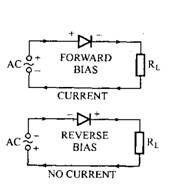
Fig. 13.23. Using a diode to rectify.
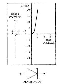
Fig. 13.24. Circuit symbol and characteristics for a 5 V Zener diode.
In automobile electronics Zener diode are generally used in voltage regulating and stabilizing circuits. These circuits maintain a constant output voltage even during fluctuations in input voltage or load conditions. Figure 13.25 illustrates a voltage regulator using a Zener diode. When the input voltage to this circuit changes, the current through the series resistor, Rs, correspondingly changes. But Zener diode holds the output to the load circuit at a constant 5 V, and all excess current passes through the Zener diode. However, the circuit cannot regulate if the input voltage is close to or below, the desired output voltage. Therefore, the input voltage must always be a few volts above the desired output voltage.
Photodiodes. A photodiode detects the presence or absence of light. The diode is connected in reverse bias so that when light falls on it extra free electrons are released in the silicon and the reverse current (normally tiny) rises sharply. A greater light intensity gives rise to a higher reverse current. In automobile electronics the photodiode is normally used in optical sensor system to detect, for example, the rotation of a disc or shaft.
Light Emitting Diodes (LEDs). A light emitting diode
(LED) emits light when current flows through it in the forward direction. Since silicon is not a good light emitter, most LEDs are made of other semiconductors such as gallium phosphide (GaP) or gallium arsenide (GaAs), and are operated at a forward voltage of about 1.6 V to produce a forward current of about 20 mA.
Depending on the semiconductor material used, LEDs are manufactured in several colours such as red (and infra-red), green, yellow and white. The LED chip is usually encapsulated in a clear plastic lens, which directs and magnifies the small amount of light coming from the semiconductor.
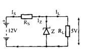
Fig. 13.25 Voltage regulation using the Zener diode.
Unlike the ordinary filament bulb, LED consumes very little power, does not get hot and goes on working almost forever. Due to small light output, the LEDs find limited applications such as sensors, dash board displays and warning lights.
Thyristor.
The thyristor, also known as a silicon controlled rectifier (SCR), is a four-layer sandwich of p- and n-type silicon (Fig. 13.26). It works as a very fast and efficient solid-state switch that never wears out. The thyristor has the symbol similar to the diode, but uses a third terminal called the gate. When forward biased, the thyristor does not conduct until a positive voltage pulse is applied to the gate. Conduction is then continued, irrespective of the gate voltage, until the supply current falls to zero.
The circuit presented in Fig. 13.26 illustrates thyristor action. Thyristor does not conduct when the power switch,

Fig. 13.26. Construction, circuit symbol and circuit application of the thyristor.
Si, is closed and the bulb does not glow. If switch S2 is now closed, the thyristor switches on (‘fires’) and conducts sufficient current so that the bulb lights brightly. The thyristor then continues to conduct, even if S2 is opened, and the bulb only goes out if Si is opened. Thyristors are capable of switching large current with a small gate pulse. For example, a 50 mA gate pulse typically switches a current of 10 A.
13.1.13.
Transistor
The transistor is perhaps the most important electrortic component of all, having the capability to amplify and produce an output signal with more power in it than the input signal. They may be used as switches like solid-state relays. Most electronic circuits use large numbers of trnasis-tors since they are cheap, fast, and extremely reliable and can be made microscopically small. Calculators and computers contain many hundreds thousands of transistors used in this way.
Since the first transistor invented in 1913, a very rapid development has been made due to which numerous different types of transistor are now available. The two types of transistor most commonly used in automobile electronics are the bipolar junction transistor (B JT) and the metal-oxide-semiconductor field effect transistor (MOS-FET).
Bipolar Junction Transistor (BJT).
The bipolar junction transistor (BJT) is a three-terminal device fabricated from two pn-junctions made in the same crystal of silicon. BJTs are available in two varieties, such
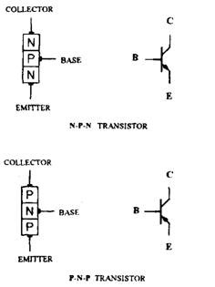
Fig. 13.27. Construction and circuit symbols ofnpn and pnp transistors.
as npn and pnp, as shown in Fig. 13.27 along with their circuit symbols. The base (B), collector (C) and emitter (E) are the three terminals of the transistor. BJTs are useful because a tiny change in current into the base terminal causes a much larger change in the current flowing between the collector and emitter terminals. Understanding of this operation of BJT is extremely complicated involving a considerable amount of mathematics, and hence, a much simplified description is provided here.
BJT as a Current Amplifier.
Figure 13.28 illustrates the application of the npn BJT as a current amplifier (the pnp device also works in just the same way, but with all the polarities reversed). In Fig. 13.28A, the potentiometer (VR) is set to have a voltage, Vbe, between base (B) and emitter (E) just a little less than G.7 V. This voltage is very significant, because silicon transistors are ‘switched off if
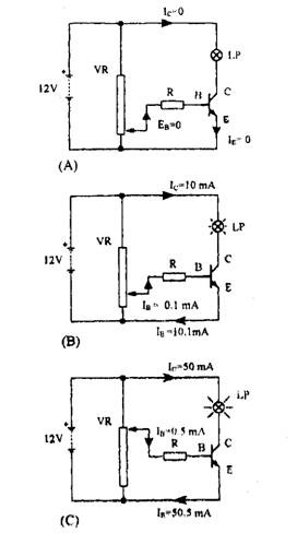
Fig, 13,38, Operation afthe npn transistor m a current amplifier,
A. Vgg is less than Q, 7 V, the transistor does net eonduet,
B. Vm is e f water thm 0,7 Vand the transistor mnduets and the lamp glows,
C. The transMer is fUHy turned an and the lamp glows brightly.
the base-to-emitter voltage (Vbe) is less than about 0.7V. In this case, since the base current (Ib) is zero, current does not flow through the transistor from collector (C) to emitter (E).
In Fig. 13.28B, the potentiometer is adjusted to have Vbe now a little greater than 0.7 V. The transistor is switched on as small base current flows into it so that a much bigger current (called collector current, Ic) flows from the collector to the emitter. The exact value of the base jcurrent depends upon the type of transistor and the value of the base resistor, R, but 0.1 mA can be assumed as a representative value. The collector current, Ic, again depend upon the type of transistor and is typically 10 to 1000 times greater than Ib. However value of Ic may be assumed as about 100 times Ib (i.e. about 10 mA), which is sufficient to dimly light the bulb.
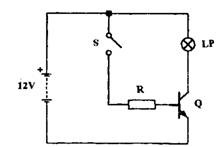
Fig. 13.29. Transistor switch.
If Ib is considered as the input signal to the transistor and Ic as the output signal, then the transistor acts as a current amplifier. The ratio of Ib to Ic, a measure of the transistor’s current gain ((3, ‘beta’), is a very important parameter for transistor. Mathematically, (3 = IcIIb. For the transistor in Fig. 13.28B, Ic – 10 mA and Ib = 0.1 mA and so, P= 10/0.1 = 100.
The current coming out of the transistor through the emitter terminal (Ie) must be the sum of the current going into the transistor (Ic and Ib). Thus, Ie = Ib + Ic- Therefore, in this example, Ie = 0.1 mA + 10 mA= 10.1 mA.
In Fig. 13.28C, the potentiometer is adjusted to the ‘maximum voltage’ position so that about 500 uA of base current flows, depending on the base resistor, R. R prevents excessive base current to avoid damage of the transistor and therefore should always be present in a circuit. Therefore, Ic = P Ib = 50 mA. This current causes the lamp to glow brightly.
A potentiometer in this example provides a varying input current, but other sources of current can also be used. Pressure, temperature and mechanical position sensors are the devices, which may need amplification of their output signals through transistors.
BJT as a Switch.
The circuit shown in Fig. 13.29 represents a transistor switch. When the mechanical switch is open, there is no base current and hence no collector current. The lamp is also off. When the switch is closed, the base-emitter voltage, Vbe, rises to about 0.7 V and the transistor turns on, lighting the lamp. Since Ic = P^B, the base resistor, R, is carefully selected to ensure the correct
value of Ib, and so the correct value of Ic.
Transistor switches are small and light, provide very rapid switching (in a fraction of a microsecond) and many circuit can be switched with a single control signal. These are the advantages of transistor switches over electromechanical relays.
Darlington Pair.
A single BJT is capable of providing a current gain of up to about 700 times its input. To have still higher gain, the Darlington pair circuit can be used. In automotive applications the Darlington pair is often used to provide large
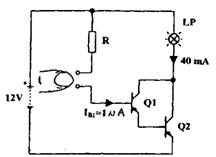
Fig. 13.30. Application of the Darlington pair in a ‘touch switch’.
amounts of current gain for driving inductive loads such as relays, ignition coils, fuel injectors and solenoid valves. Figure 13.30 illustrates the application of this circuit in a ‘touch switch’. Each transistor has a current gain, 3, of 200 and so the cascaded gain of Qi and Q2 is [3 x (3 (i.e. 200 x 200), which is 40,000.
When switch contacts are open, no current flows in the circuit and the bulb does not glow. But with a finger-end touch across the contacts, a tiny leakage current of about 1 uA flows and the current gain of the Darlington pair is then sufficient to light the bulb.
MOSFET.
Unlike the BJT, which is a current amplifier requiring a current input to control a current output, the MOSEFT is also an amplifier that uses an input voltage to control an output current. The input current to a MOSFET is usually negligible, which makes it a very low-power device.
Principle of MOSFET Operation. In contrast to the BJT, the principles of operation of MOSFET are quite easily understood. Figure 13.31 illustrates an n-channel MOSFET along with its circuit symbol (p-channel MOSFET is also used, which is made by interchanging the n-and p-regions). The basic npn silicon structure is similar to that of the BJT, and the differences arise from the method of its connection to the outside environment. The MOSFET has three metal contacts and an additional controlling terminal called a gate. The gate is insulated from the npn structure by a thin layer of silicon oxide (i.e. glass), which acts rather like a capacitor plate. As long as the voltage between the body and the gate is not positive, the device behaves like two ‘back-to-back’ pn-junction diodes and so no current passes between the n-region contacts, making the device ‘OFF’.
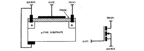
Fig. 13.31. Construction and symbol of the n-channel MOSFET.
Although the p-region has many more holes than electrons but there still some free electrons are available, and if the gate is made positive with respect to the body some of these electrons are attracted toward it (Fig. 13.32A). The gate-insulator-body sandwich structure thus forms a capacitor, which accumulates charge. As the gate is made more and more positive, the accumulation of electrons just under the gate oxide increases to the point where the electrons outnumber the holes. At this stage a small portion of the p-region (called the channel), inverts to become n-type and the device structure is now n-n-n. Current can now pass easily between the end contacts with little resistance (Fig. 13.32B),making the device ‘ON’. Gate voltage controls channel resistance (and hence the channel current).
Generally most MOSFETs have three, rather than four, leads. This happens as the body terminal is usually connected directly to one of the n-regions (Fig.13.32C).This particular
n-region is then called the source connection and the other n-region is called drain connection. To turn the device ON, the gate is made positive with respect to the source and conventional current (drain current, Id) flows from drain to source.
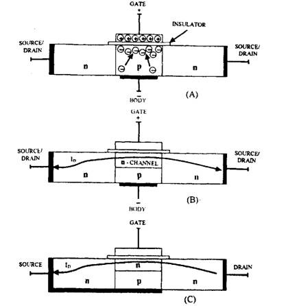
Fig.13.32. Operation of the n-channel MOSFET
A. Application of a positive voltage to the gate terminal draws free electrons to the silicon surface.
B. An n-type channel is formed and the transistor passes current between the end contacts.
C. Connection of the ‘body’ terminal to one end terminal to give ‘source’ and ‘drain’ terminals.
MOSFETs are designed for use in amplifier circuits, where Id is controlled only by the gate voltage, Vg and is almost independent of variations in the drain-to-source voltage, Vds-The MOSFET then works as a voltage-controlled current source, which is a very useful amplifying device.
MOSFET as a Switch.
The MOSFET is also used as a switch in the same way as tht BJT, except that a voltage, rather than a current, is used an the input signal, But to this MOSFET switches are mere §ffi* dent than the BJT type, and consumes about one tenth the power, so that very less heat is generated, For this reasons these
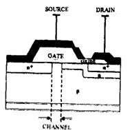
Fig, J9-.SS, Btrueture of a ‘power MOSFET’ used far emtroUmg large current,
are ideal for applications requiring large numbers of switching transistors in a small space, such as microcomputers.
‘Power MOSFETs’ with complex structures (Fig. 13.33) are also available. They are used for controlling large current and are replacing BJTs and relays for power switching in automotive electrons. Some devices (termed ‘Smart FETs’) also incorporate built-in electronic protection against excessive current or excessive temperature.
13.1.14.
Integrated Circuits (ICs)
All the discrete (i.e. separate) devices discussed so far are used maximum in integrated circuits (ICs). An integrated circuit uses a range of circuit devices (diodes, transistors, resistors, small capacitors) as well as wiring tracks, on one single substrate (generally a small tablet of silicon). Figure 13.34 illustrates the principle of a simple IC structure, however, in reality most ICs are vastly more complex.
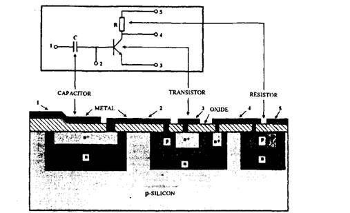
Fig. 13.34. Section through a simple integrated circuit and relationship with its circuit schematic diagram.
Since 1959, when the first integrated circuit was developed, enormous numbers and varieties of ICs are produced. Due to it’s low cost, high reliability and small size, the ICs now find place almost in every electronic control unit (ECU) used in automobiles. ICs are available for nearly every electronic circuit function. Whenever a particular function is not catered for with the available ones, an IC manufacturer usually designs a chip to order. These ‘custom chips’ (called application-specific integrated circuits, or ASICs) are widely used by vehicle manufacturers, and even in some cases have their own ‘in-house’ASIC design and production facilities.
Hybrid Integrated Circuits.
The integrated circuits discussed so far are called a monolithic IC. Figure 13.35 illustrates the structure of a different type of IC, called a hybrid IC. It has discrete components, such as diodes, transistors, resistors and capacitors, as well as monolithic ICs, all integrated on a common glass or ceramic substrate. Although hybrid ICs constitute only a small fraction of the
total number of ICs in production, they have established a place in automotive electronic systems. This is because the automotive design cycle is now very short and the development time required for a hybrid IC is often shorter than that for a monolithic IC. Moreover, the hybrid IC is generally able to handle higher voltages and larger current than its monolithic counterpart.
Analogue and Digital Signals.
When a varying voltage or current is used to convey information from one place to another it is called a signal. For example, it may be a signal for the temperature of the engine coolant, or the quantity of fuel in the tank. In electronics two categories of signal are dealt ; (i) analogue signals, and (ii) digital signals.
Analogue signals are voltages or currents that vary with time in a smooth and continuous manner, and can have any value within a specified range (Fig. 13.36A). The information in an analogue signal is contained in the instantaneous value of its voltage or current. For example, if a coolant temperature of 10 K is indicated by a 1V signal, then 100 K might be indicated by a 10 V signal and 400 K by a 40 V signal. Analogue circuits are used to process analogue signals. Transistors are used as amplifying elements in these circuits.
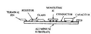
Fig. 13.35. Section through a hybrid IC.
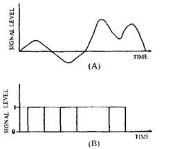
Fig. 13.36. Analogue and digital signals.
A. The analogue signal can take any value within a specified range.
B. The digital signal can take one of only two specified voltages.
Digital signals (Fig. 13.36B) can have only two possible voltage levels; an ‘ON’ voltage (usually the supply voltage), and an ‘OFF’ voltage (usually 0 V). The information in a digital signal is conveyed either through the timing of the digital pulses, or as a coded binary number,
indicated by particular sequence of ‘ON’ and ‘OFF’ pulses. Digital signals are processed by digital circuits, where transistors are used simply as switching elements.
Integrated circuits may be of the analogue or the digital type and may use BJTs, MOSFET or a combination of both. Some ICs are known as mixed-signal ICs, which contain both digital and analogue circuitry on the same chip. Most of the circuits used in automobile electronic control units (ECUs) are digital ICs, however, a small number of analogue ICs are also used.
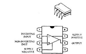
Fig. 13.37. A typical 8-pin duel-in-line (DID op-amp package and terminal connections.
Analogue Integrated Circuits.
The operational amplifier (usually shortened to ‘op-amp’) is one of the most versatile analogue ICs. An op-amp, a very high performance amplifier, uses about 20 to 30 transistors, and develops a voltage gain in the region 500,000 to 1,000,000. Most op-amps are available in an 8-pin dual-in-line (DID IC package and to identify the function of each pin, the manufacturer’s data sheet is to be referred. A typical op-amp package, along with its terminal connections is shown in Fig. 13.37.
A signal entering terminal 3 (the non-inverting input) emerges from terminal 6 (the output) with no change in shape, but with voltage gain. The same signal entering terminal 2 (the inverting input) also emerges from the output with voltage gain, but in an inverted (upside down) state of the shape. The op-amp thus acts as a differential amplifier by amplifying the difference in voltage between the inverting and non-inverting inputs. If the same signal is applied to both inputs, then no signal is received from the output terminal.
Based on the input connections made, and the way the external components such as resistors, capacitors and diodes are connected, the op-amp can perform many varieties of
analogue functions. The comparator is one of the most common op-amp functions used in automobile ECUs.
Comparator.
A comparator does a comparison between the voltages applied to its two inputs and provides a binary output. In automobiles, a comparator is commonly used to compare the input from a sensor (a thermistor, potentiometer, etc.) with a fixed reference value.
Typically, when the non-inverting terminal voltage is greater than the inverting terminal voltage, the op-amp’s output is approximately equal to the supply voltage. Conversely, when
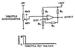
Fig. 13.38. Schmitt trigger comparator circuit used to detect when a throttle potentiometer is at the idle position.
the inverting terminal voltage is greater than the non-inverting terminal voltage, the output is approximately 0 V. Figure 13.38 illustrates a typical comparator circuit called a Schmitt trigger. The voltage from a throttle position potentiometer is fed to the inverting terminal of the Schmitt trigger and compared with a fixed reference voltage of 0.5 V (set by R\ and #2). A third resistor (i?3) is used to provide hysteresis. This alters the reference voltage slightly when the output is ‘low’ and so makes the comparator more tolerant of a ‘noisy” input signal.
When the output from the throttle sensor is below 0.5 V the comparator output becomes ‘high’, indicating a closed throttle. When the throttle is opened, the comparator input voltage rises above 0.5 V and its output becomes ‘low’. The engine ECU microprocessor uses this signal, along with other signal relating to vehicle speed, to decide whether or not to operate engine idle speed control.
Digital Integrated Circuits.
Digital circuits recognize input signals as either high’ (near to the supply voltage) or ‘low’ (near to 0 V). Engineers normally term these as ‘H’ and ‘L’ or ’1′ and ’0′ logic states. Minor variations in the ’1′ and ’0′ voltages are ignored by digital circuits, so that the digital signals
particularly become resistant to electrical noise. Circuits that provide output for a particular logic state in response to a particular set of input logic states are known as logic circuits or logic gates.
Digital logic ICs are available in two main varieties : (i) TTL (transistor-transistor logic), which uses many interconnected BJTs, and (ii) CMOS (complementary metal-oxide-semiconductor), which contains inter connected pairs of p- and n-MOSFETS.
TTL chips can switch very fast between logic states. These are frequently used for high-speed processing of digital signals. However, they consume quite lot of power an require an accurately regulated 5 V supply. CMOS ICs are slower than TTL, but provide several benefits such as much lower power consumption, greater noise tolerance and a wide operating voltage range of from 3 V to 15 V. Therefore, automobile circuit designers prefer to use CMOS ICs wherever possible.
