26.5.
Differential
Purpose.
When both rear wheels are connected to a common driving^shaft rapid wear of\rear tyre, and difficulty in steering from the straight-ahead position are soon experienced. It canNbe seen in Fig. 26.43 that the outer wheel must travel a greater distance than the inner wheels during cornering of the vehicle. Hence, if the wheels are interconnected, the tyres have to ‘scrub’ over the road surface and tend to keep the vehicle moving straight ahead. These problems can be minimized by driving one wheel and allowing the other to run free. But this provides unbalanced driving thrust and unequal cornering speeds due to which the arrangement was not accepted. The problem was solved in 1827 by Pequeur of France who invented the differential. This mechanism rotates the wheels at different speeds, while maintaining a drive to both wheels.
Example 26.4. The steering set of a, vehicle provides a turning-circle radius of 6.6 m with a wheel-track width of 1.2 m. The effective road wheel rolling diameter is 0.72 m. Calculate the number of revolutions made by the inner and outer wheels for one turning circle.


Fig. 26.43. Need for differential.
![]()
The differences = (20 – 16.6) = 3.4 revolutions between ^he inner and outer wheels for one complete turning circle of wheels. This difference must be absorbed by tyre scrub or accommodated by some mechanical device.
Principle.
Consider the two discs, illustrated in Fig. 26.44A, are joined by shafts to the wheels and interconnected with a lever. When a force, F, is put to C at the centre of the lever, each disc receives half the applied force. The movement of the discs depend on the resistances, R, opposing the motion of the shafts. If a larger resistance acts on disc ‘B’, the lever tilts, and pushes disc ‘A’ forward a greater amount. This condition is illustrated in plan view in Fig. 26.44B and the increase in distance travelled by A equals decrease in distance travelled by B, and increase in speed of A equals decrease in speed of B.
Therefore, A + B = 2C.
The disc system is replaced by bevel gears in Fig. 26.44C, called sun wheels (disc) and planets (levers). The drive, applied to the cross pin, pushes the planet gears forward and exerts an equal
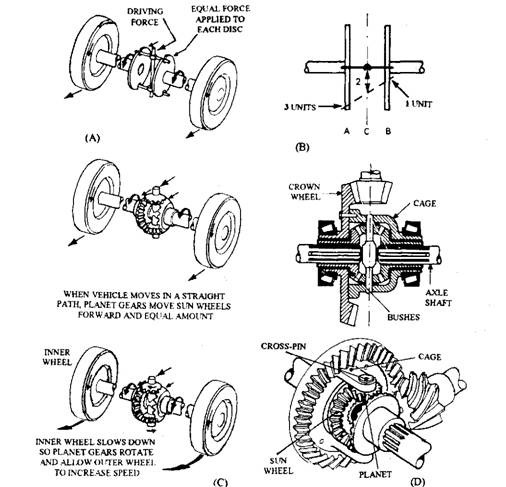
Fig. 26.44. Action of differential.
torque on each sun wheel irrespective of the speed. When the vehicle negotiates corner, the inner wheel slows down and the planets rotate on their own axis allowing the outer wheel to speed up. During straight-ahead movement of the vehicle the whole unit rotates at the same speed.
A differential unit is shown in Fig. 26.44D in which a crown wheel is bolted on to a differential cage. This cage also carries the sun wheels on plain bearings and transmits the drive to the cross pin. Two planet gears are sufficient for light vehicles but four gears are necessary in heavier vehicles to reduce tooth pressures. The differential is lubricated by the final-drive oil, which splashes through holes in the differential cage.
Differential Lock.
In a two-wheel drive vehicle if one driving wheel loses adhesion, the propelling force is considerably reduced. This results in the immobilization of the vehicle so that the differential action becomes undesirable on the vehicles designed to operate over poor surfaces. This action can be prevented by locking together any two individual units of a differential. One such arrangement is illustrated in Fig. 26.45. A sliding dog clutch member is splined to a differential sun wheel, which engages with dog teeth formed on the cage of the differential. The clutch is engaged by means of a fork, which can be moved by a lever fitted on the outside of the axle. When engaged, the sun wheel, and hence the rear wheel connected to this sun gear, is made to turn at the same speed as the cage. Locking one sun gear to the cage in this way ensures that the other sun gear also turns at the same speed.
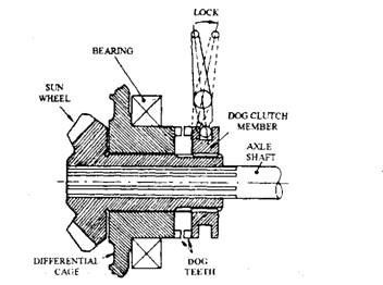
Fig. 26.45. Differential lock.
Limited-Slip Differential.
A differential does not provide a high mechanical efficiency, which is desirable for the majority of mechanical components. Even if a ‘low friction’ differential with reduced traction over slippery surfaces is fitted, it limits acceleration of a high-power vehicle and causes excessive tyre wear. The torque reaction of the engine of such a vehicle, during acceleration, tends to lift the left-hand driving wheel off the ground. When accompanied by an uneven road surface, this causes excessive wheel spin. To minimize these drawbacks, the differential action is counteracted by artificially increasing the friction between the sun wheel and the differential cage. When this feature is included, it is called limited slip differentials. Two basic types of limited slip differential are :
• Mechanical limited-slip differential. • Visco-differential.
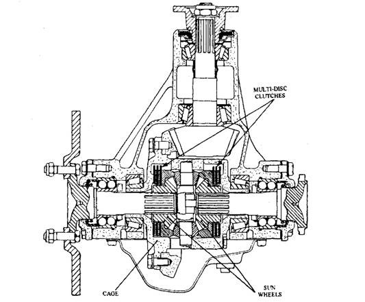
Fig. 26.46. Final drive assembly with limited slip differential.
26.5.1.
Mechanical Limited-slip Differential
Figure 26.46 illustrates a limited-slip differential, which is bolted to the crown wheel. A multi-disc clutch pack mounted behind each sun wheel has the inner and outer plates splined to the sun and cage respectively. The bevel gears exert an axial thrust proportional to the torque applied by the crown wheel to the differential. Under low torque transmission, the differential functions in the normal way. When transmitted torque is increased, the clutch pack is loaded, which resists motion of the sun gear so that it rotates at a different speed than that of the cage (Fig. 26.47).
To operate with further increase of the load on the clutch pack, the additional features are incorporated in many designs. These include the following:
(i) The discs are provided with an initial load through a Belleville disc-spring washer
installed between the cage and the clutch discs of each pack. (ii) Angled cam faces are installed between the cage and the cross pins. The cage exerts driving thrust on the pin, which in turn forces the planets against the side gear ring. In a four planets system, two separate pins are flexibly linked at the centre with opposite cam faces, so that they cause two planets to act on one clutch pack and the other two to exert force in the opposite direction.
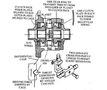
Fig. 26.47. Limited slip differential.
26.5.2.
Viscous Differential
This type combines a standard differential unit with a viscous coupling. The coupling is used in this system as a viscous control device to regulate the speed difference between the two driving wheels. As explained above the locking action on a mechanical limited-slip differential depends on input torque, whereas on the viscous type it depends on the speed difference of the driving wheels. Very little resistance is offered with a small speed difference and this increases progressively with the increase of the difference. Compared with the mechanical limited-slip differential, the viscous type provides lower tyre wear, easier steering and lower stresses in driveline components. For high-viscosity fluid, the coupling can be designed to deliver a comparatively high torque, which progressively builds up with the increase of shear rate.
The visco unit is very similar in basic construction to a multi-plate clutch. It uses a housing and hub, and a series of perforated metal plates submersed in silicon fluid (Fig. 26.48) are sandwiched between them. Also these plates are alternatively attached to the hub and housing. A fluorinated rubber heat resistant seal isolates the silicone fluid from the lubricating oil in the final drive assembly.
The torque and shear rate relationship depends on fluid viscosity, the gap between plates and plate perforation. These factors are varied while designing a coupling suiting to the application.
Prolonged slippage of the coupling causes generation of heat due to which the fluid expands and occupies some of air space. In case spacers are not used to position the plates apart, the increase in air pressure due to fluid expansion and the reduction in fluid pressure in the gaps pushes the plates together. This causes metal-to-metal contact so that the coupling temporarily departs from its viscous mode operation. During this phase the torque output rises considerably even six times as great in some designs.
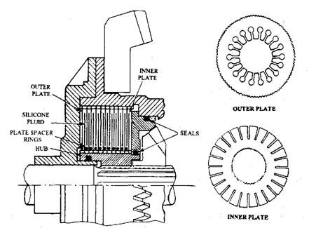
Fig. 26.48. Visco-differential.
Viscous couplings can be used to control front, centre and rear differentials. Each application can be considered as different in view of its position, speed of operation and type of vehicle to which it is fitted. For example, a viscous control unit at the rear of a powerful car requires the use of’hump’ as overload protection. But, viscous coupling used for a front wheel drive car should have no ‘hump’, because a unit with this characteristic would adversely affect the steering. The viscous control unit can be installed and connected in a differential in two ways; i. e. shaft-to-shaft and shaft-to-cage couplings.
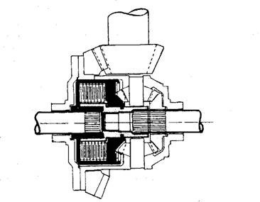
Fig. 26.49. Shaft-to-shaft viscous coupling.
Shaft-to-shaft Viscous Coupling.
A bevel-type differential having a viscous control unit connected between the two axle shafts is illustrated in Fig. 26.49. The hub holding and inner plates is joined to one shaft, and the housing with its outer plates is connected to the other shaft. The unit is installed at the centre of the crown wheel by moving the differential to one side. The control unit does not function during movement of the car in a straight path with no wheel slip. But, if the shaft speed becomes different, such as when one driving wheel loses adhesion or when wheel spin occurs during acceleration, the resistance offered by the unit maintains equal driving torque to both wheels.
Shaft-to-cage Viscous Coupling.
In the layout illustrated in Fig. 26.50, the housing of the viscous control unit is integral with the differential cage and the hub is connected to one axle shaft. This arrangement is comparatively cheaper. The speed difference between the cage and axle shaft is half the difference of the road wheels. Therefore, compared with the shaft-to-shaft layout, the shaft-to-cage arrangement exhibits a torque characteristic about three times greater to have the same locking effect.
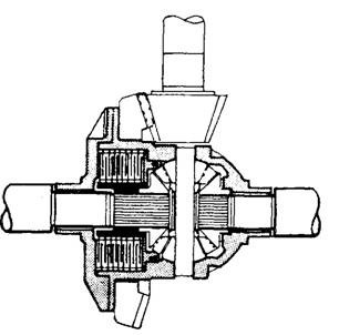
Fig. 26.50. Shaft-to-cage viscous coupling.
