24.5.
Diaphragm Spring Clutch
Diaphragm-spring clutch has similar construction to that of the multi-coil spring unit, but it uses a single dished diaphragm-type spring to apply the clamping thrust. This spring also serves as part of the release mechanism. Figures 24.6A and B represents two types of clutches.

Fig. 24.6. Diaphragm-spring clutch assembly (Borg and Beck) A. DS-type clutch. B. DL-type clutch.
The diaphragm spring (Fig. 24.5A) is a steel disc having a hole at the centre, and the inner portion of the disc is radially slotted so that a number of actuating (release-lever) fingers are formed. The outer ends of the slots are provided with enlarged blunting holes, which distribute the concentrated stresses created during deflection of the fingers, and also provide a means of locating the shouldered rivets, which restrain the fulcrum rings.
The diaphragm spring is placed between the pressure-plate and the cover pressing (Figs. 24.6A and B). The outer edge of the dished spring bears against the pressure-plate, and two round-sectioned wire rings are positioned from a short distance from its outer edge, one on each side of the dished spring. These two rings are located as well as held in position by shouldered rivets and these rivets in turn are supported by the cover pressing (Fig. 24.7).
During fastening of the cover-pressing to the flywheel, the dished spring is slightly flattened, which loads the pressure-plate against the driven friction discs, the spring reaction being taken
through the outer ring to the cover-pressing. The inner ring acts as a pivot point for all the individual release-lever fingers and are located near the periphery of the diaphragm spring to increase the leverage.

Fig. 24.7. Rigid driven-plate and diaphragm-spring clutch assembly.
The clutch actuating linkage causes the release bearing to press against the release-fingers to disengage the clutch. These pivot and tilt about the inner ring, thereby the spring’s cone angle is increased, and the spring thrust load is relaxed or withdrawn from the friction faces of the

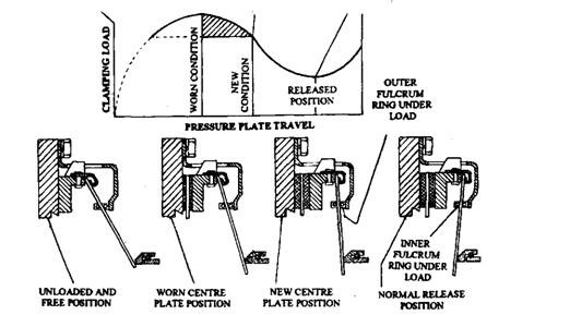
Fig. 24.8. Pressure plate travel vs various condition of plate assembly units.
driven-plate. Retractor clips are provided so that the diaphragm spring can withdraw the pressure-plate from the flywheel. This interrupts the drive between the engine and gearbox.
With a new driven-plate, the dished spring is almost flat and so it cannot exert maximum thrust load against the pressure-plate. As the wearing of the driven-plate friction discs occurs, the spring automatically expands towards the flywheel, which reduces the cone angle and increases the dishing of the spring, enabling initially a greater clamping thrust to be exerted. With further wear, the distortion results in the release-fingers so that they are over relaxed due to which their force in the pressure-plate decreases reducing the thrust load (Fig. 24.8).
The small-torque-capacity clutches incorporate three lugs cast with the pressure-plate, which engage slots aligned in the cover-pressing (Fig. 24.6B) thereby transfer the drive from the cover-pressing to the pressure plate. On the other hand the larger clutches tend to have three straps, one end of each being attached to the cover pressing and the other end to the pressure-plate (Fig. 24.6A) for transferring the drive.
The release bearing assembly enables the stationary clutch foot-pedal linkage to transmit the disengagement leverage to a rotating clutch assembly. Two basic types of systems are in use for this operation. In one, a release-plate is fitted to the release-fingers and a carbon saddle-type release bearing presses thin plate to disengage the clutch (Fig. 24.6A). In other, a ball thrust-race assembly acts directly against the release-fingers when releasing the driven plate (Fig. 24.6B).
