3.3.
Cylinder Head
The cylinder head is a casting bolted to the top of
the cylinder block. It houses the inlet and exhaust
poppet-valves, houses the spark-plug or injector loca-
tion holes, forms the upper face of the combustion
chamber, and takes the combustion-pressure reac-
tion. The coolant passages, cavities, intake and ex-
haust ports, lubricating passages, and the spark plug
or injector bosses (Fig. 3.19) are also located within or injector bosses (Fig. 3.19) are also located within
the head casting.
The cylinder head is detachable for easy access to
the valves and piston tops and to facilitate machining
of the cylinder bore, combustion chamber and valve
ports. The mating faces of the cylinder head and block
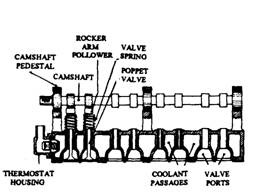
Fig. 3.19. Four-cylinder overhead-camshaft
cylinder head.
are ground flat, so that a sandwiched gasket is squeezed in between when the head is bolted
down forming a liquid-tight and gas-tight joint.
3.3.1.
Cylinder-head Materials
The cylinder head material should be readily cast with complicated internal shapes for both
the coolant passages and for the inlet and exhaust ports. The material should be strong enough
in compression and able to operate continuously under fluctuating gas pressures and tempera-
tures when fixed rigidly to the cylinder block by bolts or studs. Although the gas-pressure loads
are not excessive for the available materials, but prevailing temperature gradients produce
non-uhiform expansion and contraction of the metal in these regions. As a result, thermal
stresses are developed across the cylinder head eventually causing distortion or even cracks in
the critical areas exposed to the heat of combustion.

(A) (B)
Fig. 3.20. Shapes of combustion chamber.
A. Hemispherical chamber. B. Wedge chamber.
The ideal cylinder-head material should limit the temperature of the surface so that
lubrication remains effective, combustible petrol-and-air mixtures do not overheat to cause
detonation, hot spots that promote pre-ignition are not formed, and high cyclic thermal stresses
are not developed. In particular, under various operating conditions like continuous full-load
running on motorways or under part load operations with weak mixtures and late ignition,
surface temperatures rise causing local thermal stresses, which can easily reach dangerously
high values unless the heat is adequately dissipated.
The materials generally used are grey cast iron and aluminium alloys. The common
cylinder-head cast iron meets most of the requirements, such as cheapness, good castability,
good machinability, good corrosion resistance, adequate rigidity, strength, and hardness, and
low thermal expansion. But it has the disadvantages of high weight and low thermal conduc-
tivity.
The aluminium alloy head, on the other hand, has half the weight of equivalent cast-iron
heads. It also has a thermal conductivity three times better than that of cast iron due to which
the possibility of thermal distortion is reduced and the head cooling system permits the use of
higher compression-ratios. The disadvantages of aluminium alloy are that it is more expensive,
it’s corrosion resistance is inferior to cast iron, it is much softer than cast iron, and it has a high
thermal expansion which causes fretting between an aluminium-alloy head and a cast-iron
cylinder block during starting and stopping of engines, so that separate wear-resisting valve
seats and guide inserts become necessary.
The composition of the cast iron used in cylinder heads is similar to that used in cylinder
blocks (section 3.1). In the case of aluminium alloys, however, slightly different compositions
are preferred. Two commonly recommended aluminium-alloys are
(i) 3.0% copper. 5% silicon, 0.5% manganese in a matrix of aluminium; and
(ii) 4.5% silicon, 0.5% manganese, 0.5% magnesium in matrix of aluminium.
The copper and silicon in the alloys reduces thermal expansion and contraction and
improves the fluidity and castability properties of aluminium. Copper promotes age-hardening
and silicon improves the abrasion resistance. Addition of manganese and magnesium improves
the strength of the alloy. The corrosion resistance of the slightly superior alloy containing copper
is inferior to that of the copper-free silicon-aluminium alloy.
3.3.2.
Petrol Engine Combustion Chambers
The cylinder head forms the top of the combustion chamber. The combustion reactions in
the combustion chamber vary depending on the type of fuel, combustion chamber shape, cooling
system efficiency, locations of the spark plugs and valves, the compression ratio and the quality
of the intake charge. The combustion chamber shape, one of the most important of these factors,
primarily depends on the shape of the top of the piston and the shape of the pocket formed in
the cylinder head. These shapes have a great effect on the control of combustion smoothness.
Combustion chambers are of two types such as non-turbulent hemispherical chamber (Fig.
3.20A) and turbulent wedge chamber (Fig. 3.20B).
In non-turbulent hemispherical chambers, combustion radiates out from the centrally
located spark plug and hence is completed in the least possible time. The end gases that cause
abnormal combustion have little time to react and therefore knock is reduced to a minimum.
The rapidly burning charge causes a high rate of pressure rise, which produces some engine
roughness and noise under medium and heavy loads at low engine speeds. This may be
objectionable to the passengers. The hemispherical chamber is best suited for racing cars.
The turbulent wedge combustion chamber is designed to produce a uniform burning rate by
controlling combustion through changes in the combustion chamber shape, resulting in smooth
power production. The piston, towards end of the compression stroke, approaches a low or flat
portion of the head called the squish area or quench area. Gases are squeezed out of this area
into the larger portion of the combustion chamber producing turbulence within the charge. Since
the spark plug is positioned in the highly turbulent part of the charge, ignition is followed by
smooth and rapid burning. The end gases remaining in the squish area are squeezed to a very
thin layer less than 0.25 mm thickness when the piston is at the top dead centre, and are cooled
and hence do not react. The charge adjacent to the combustion chamber surface forms 0.005
mm to 0.050 mm thickness and doesn’t burn as the temperature of the charge is below its ignition
temperature.
Hemispherical combustion chambers, with low surface area compared to their volume, emit
less unburned hydrocarbons than the wedge combustion chamber, which has a relatively high
surface area to volume ratio. Improvement in combustion chamber design has been added by
changing the valves of the wedge head to divergent angles, repositioning the spark plug,
reducing the quench area and reducing the combustion chamber surface area to volume ratio.
Some examples of such modified chambers are the polyspherical, semi-wedge and kidney
shapes.
The cylinder head, shown in Fig. 3.21A, has a turbulent generating pot (TGP), which
produces high turbulence or swirl of the air-fuel mixture during combustion. A part of the
mixture is forced into the pot during compression. This burns first on ignition and streams out
at high velocity. This helps rapid spread of the flame resulting in better combustion.
In the precombustion chamber arrangement (Fig. 3.21B) there is a pot with a small valve
and the spark plug. A lean mixture enters the main combustion chamber. A rich mixture enters
the precombustion chamber where ignition takes place. The hot burning gases rush into the
lean mixture, ignition it. This produces good turbulence and rapid burning of lean mixtures,
and thus minimizes emissions.
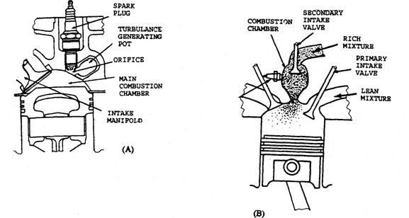
Fig. 3.21. Cylinder.
A. With turbulence generating pot. B. With precombustion chamber.
3.3.3.
Diesel Engine Combustion Chambers
In diesel engines the combustion chamber plays an important role in engine performance.
The chamber must be designed to provide uniform mixing of the compressed air and injected
fuel. There are many good designs of CI combustion chambers, where each one is shaped to
achieve an effective swirl pattern. These designs can be divided broadly into two main following
classes :
(i) Direct injection
(ii) Indirect injection
In the former type, fuel is injected directly into the closed end of the cylinder, whereas in
the latter type, fuel is sprayed into a separate small chamber, which is connected to the cylinder
by a small passage or throat.
Direct Injection.
Figure 3.22 illustrates the fundamentals of a direct injection (DI) type combustion chamber,
which has been used in heavy vehicles since many years and, in a slightly modified form, is
currently being used for car engines in the 2-litre capacity.
Since at TDC the piston is very close to the flat cylinder head, a deep cavity, machined in
the piston, contains most of the air. To obtain the necessary compression ratio, overhead valves
are necessary. Shallow recesses in the piston crown provide clearance for the valve heads.
However, inaccurate setting of the valve timing causes the valves to strike the piston. A
multihole injector allows finely atomized fuel under high pressure (17 MPa) to penetrate the
fast-moving air and just enter the cavity of the piston.
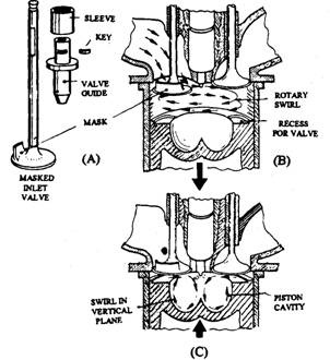
Fig. 3.22. Direct injection combustion chamber.
Swirl is generated in both vertical and horizontal planes. The ascending piston directs the
air into the cavity, which moves in the manner shown in the figure. As the piston approaches
TDC, this motion is speeded up because of the squish action of the air between piston and head.
Horizontal or rotary swirl can be obtained by inclining the inlet port tangentially to the cylinder,
or masking the inlet valve. Figure 3.22A illustrates the latter arrangment, which is the most
popular. Combining both swirl movements produces a vortex air flow in the cavity, and ensures
a good supply of oxygen to the combustion region.
Indirect Injection.
Until the mid-1980s the indirect injection (IDI) type was commonly used in small CI engines
fitted in light vehicles. Compared with the traditional heavy vehicle DI engine, the IDI runs
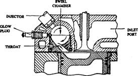
Fig. 3.23. Indirect injection combustion chamber
(Swirl chamber).
more smoothly and since the IDI types uses lower
injection pressures, the engine is able to operate
over a large speed range.
Many IDI combustion chambers are shaped
based on the Ricardo Comet design illustrated in
Fig. 3.23. In this arrangement a swirl chamber
is connected to the main chamber by a throat,
which operates at a higher temperature than the
surrounding metal.
Air is pushed through the hot throat into the
chamber during compression, therefore by the
end of this stroke the ante-chamber contains very hot air in a high state of swirl. Fuel, injected
into this fast moving air mass, is quickly atomized into a very fine state. This atomization is
extremely effective even though fuel is injected in the form of a ‘soft’ spray by a pintle or
single-hole nozzle set at a comparatively low pressure of the order of 9.8 MPa.
Once combustion is initiated in the swirl chamber, burning fuel together with the unburnt
and partially burnt fuel is carried into the piston cavity in the main chamber. If the injection
period is extended to produce a higher engine power, most of the fuel, injected towards the end
of the spraying period, does not ignite until it mixes with the air in the main chamber. This
ensures continuation of the burning for a relatively long time until it finally attains a stage at
which the fuel cannot find sufficient oxygen. Beyond this point black smoke starts to emit from
the exhaust. This point of start of smoke indicates the maximum quantity of fuel that can be
injected without sacrificing economy and also represents the maximum power that can be
obtained from the engine.
In an IDI engine the combination of hot air and excellent atomization gives a short ignition
delay. Compared with the DI type, in IDI engines the intensity of diesel knock is lower, the
engine runs more smoothly and the required cetane rating of the fuel can be lower. The DI
engines have compression ratios of about 16:1, but the IDI engines use higher ratios of the order
of 22:1 and in some cases as high as 30 : 1. In addition to the cold-starting requirement, a high
compression ratio in IDI engines also improves the thermal efficiency, i.e. economy, as compared
to that of the DI engine. This feature also somewhat counteracts the greater heat loss due to
the larger surface area of an IDI combustion chamber.
Cold Starting.
All CI engines need some special arrangement for cold starting. Although the injection of a
larger quantity of fuel and the greater percentage of easily ignitable fractions contained in the
injected charge are generally sufficient to start a cold DI engine, the larger heat losses in IDI
units require these engines to have additional cold-start facilities.
For cold-starting of a CI engine, one or more of the following methods are used :
(a) Heater plug, often called a glow plug or hot bulb in fitted is the swirl chamber. The
air in the chamber is heated electrically for a few seconds prior to starting a cold engine.
Now-a-days these plugs are often controlled automatically.
(6) Manifold heaters, an electrical unit, are fitted to pre-heat the air as it passes through
the inlet manifold to the cylinder.
(c) Pintaux injector, a pintle-type injector, has an auxiliary hole to direct fuel down the
throat of the chamber during the cranking period.
A glow plug (Fig. 3.24) is installed in each precombustion chamber next to the injector. When
the ignition key is turned on, the glow plug tips become cherry red with a temperature of about
1310 K. A glow indicator light turns off when the glow plugs are sufficiently warm to start the
engine. Once the engine has started, a timer keeps the glow plugs to continue glowing
(after-glow) until the engine reaches a certain temperature. After-glow helps to improve cold
engine operation and reduce white smoke. A typical glow system wiring schematic is shown in
Fig. 3.25.

Fig. 3.24. Aglow plug.

Fig. 3.25. Aglow plug system wiring.
3.3.4.
Intake and Exhaust Ports
The intake and exhaust systems
are designed to meet the engine’s
maximum power requirements with
minimum restriction. At the same
time, the intake system provides
satisfactory charge distribution in
the induction system at part throttle
and idle speeds.

Fig. 3.26. Cylinder head with Siamesed ports.
The intake and exhaust ports are passages cast in the cylinder head leading from the
manifolds to the respective valves. An optimum design is not always possible because of spade
requirements for head bolt bosses, valves guides, cooling passages, and push-rod opening
clearance. In-line engines have both intake and exhaust ports located on the same side of the
engine. Therefore, often two of the cylinders share the same port because of the restricted space
available. These ports are called Siamesed ports (Fig. 3.26). Siamese intake ports are common
in in-line engines but rare in V-type engines. Larger ports and better breathing is possible in
engines that have the intake port on one side of the head and the exhaust port on the opposite
side. In these engines, a separate port is usually provided for each cylinder (Fig. 3.27).

Fig. 3.27. Cylinder head with individual ports.
3.3.5.
Coolant Passages
Coolant flows from the coolest portion
of the engine to the warmest portion.
Coolant is fed into the block where it is
directed all around the cylinders, after
which it flows upward through the gasket
to the cooling passages cast into the
cylinder head. The heated coolant is col-
lected at a common point and returned to
the radiator for cooling before it is
recycled.
Relatively large openings are
provided in the gasket surface of the head
into the head cooling passages. They are
necessary because the cooling passage
core is supported through these openings
during casting of the head. The openings
between the head and the block are nor-
mally too large for the correct coolant
flow. In this case, the head gasket per-
forms an important role by providing a
calibrated restriction with punched holes
for correct flow of coolant at each opening
(Fig. 3.28). Therefore, the head gasket
must be installed correctly for proper engine cooling.
Special cooling nozzles or deflectors are incorporated into the head to direct coolant to the
portion of the head where localized heat is required to be removed, for example the area of the
exhaust valve. Some of the deflectors are cast in the cooling system, while others are pressed-in
sheet metal nozzles.
3.3.6.
Lubricating Passages
Lubricating oil is supplied to the over-head valve mechanism either through the valve
push-rods (Fig. 3.29) or through drilled passages in the head and block casting (Fig. 3.30). The
head gasket has special openings to allow the oil to pass between the block and head without
leakage. From the valve mechanism, oil returns to the oil pan through oil return passages. These
comprise of drilled holes in some engines or relatively large cast holes in most engines fdr
reducing total engine weight and thereby the cost.
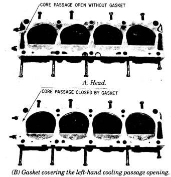
Fig. 3.28. Coolant flow control.
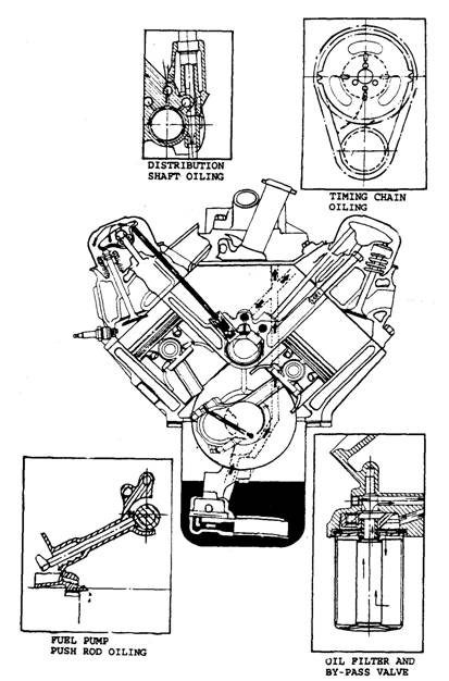
Fig. 3.29. Valve gear lubrication through hollow push rods.
3.3.7.
Stud, and Set-bolt
The cylinder head is placed on the top deck of the cylinder block and both are joined together
by either studs or set-bolts. When the cylinder head is being screwed down to the block it is in
compression and therefore the studs or set-bolts are in tension. This action pulls out and strains
the metal around the threaded region on top of the cylinder block (Fig. 3.31). To provide sufficient
joint strength, the depth of the threaded counter bore should be at least twice the diameter of
stud of setbolt, and the threaded cut in the block should start at least 0.3 times their diameter
below the surface (Fig. 3.31).
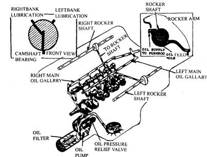
Fig. 3.30. Drilled oil feed passages in the block and head for valve lubrication.
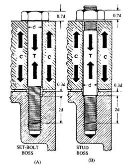
Fig. 3.31. Counter boring for cylinder head and threaded cylinder head and threaded cylinder block
holes for stud or set-bolt.
The hold-down screw holes should be as close as possible to the bore, otherwise the joint
faces tend to pull open during combustion, thereby reducing their squeeze and sealing effective-
ness. But if the holes are too near the top of the cylindrical bore they distort out of roundness.
With an aluminium-alloy cylinder head set-bolts should always be used; otherwise it becomes
almost impossible to withdraw the head over studs if any corrosion products are formed between
the studs and their respective holes in the cylinder head.
The minimum number of threaded hold-down holes in the top deck of the block is four, or
in some cases five for engines with each cylinder capacities up to about half a liter. Above this
cylinder capacity, six, seven, or sometimes even eight or nine hold-down screws are used.
The recommended material for good quality hold-down studs or set-bolts is manganese-
molybdenum steel, a typical composition of which is 0.35% carbon, 0.2% silicon, 1.6% man-
ganese, 0.3% molybdenum and 97.55% iron. After heat treatment, the mechanical properties of
this steel become :
Tensile strength = 1000 N/mm2
Yield strength = 800 N/mm2
Impact toughness = 47 Joules
Hardness = 290 to 340 Brinell
The safe working strength for this steel is 640 N/mm which is usually taken as 80% of the
yield strength of the steels.
