Engine Construction
The major components of an automobile reciprocating piston engine are the
cylinder block, oil pan, cylinder head, intake manifold, exhaust manifold, crankshaft,
flywheel, camshaft, oil seals, bearings, connecting rod, piston, piston rings, valve
train etc. This chapter deals with all these components with respect to their function,
construction, design considerations, materials, trends, etc.
3.1.
Cylinder Block
The cylinder block is the portion of the engine between the cylinder head and sump (oil pan)
and is the supporting structure for the entire engine. All the engine parts are mounted on it or
in it and this holds the parts in alignment. Large diameter holes in the block-castings form the
cylinder bores required to guide the pistons. These holes are called bores as they are made by
boring. The cylinders are provided with a web or bulkhead to support the crankshaft and head
attachments. Each main bearing bulkhead supports both a cam bearing and a main bearing.
The bulkhead is well ribbed to support and distribute loads applied to it. This gives the block
structural rigidity and beam stiffness. The cylinders are surrounded by cooling passages. The
block has drilled passages for the flow of coolant and lubricating oil separately. When a curved
passage is needed, intersecting drilled holes are used. After oil holes are drilled the unneeded
open ends are capped by pipe plugs, steel balls, or cup-type soft plugs. The head, pan, and timing
cover are fixed to the block with sealed joints for eliminating leakage. Gaskets are used in the
joints to take up machining irregularities and to absorb variations due to pressure and
temperature extremities.
Within the cylinder, combustion process produces rapid and periodic rises in temperature
and pressure. These induce circumferential and longitudinal tensile stresses, which act around
the cylinder and in the direction of the cylinder axis respectively. These induced stresses are of
pulsating nature, so that the cylinder is continuously stretched and contracted while in
operation. Combustion pressure loads are carried from the head to the crankshaft bearings
through the block structure. Mounting pads or lugs on the block transfer the reaction loads
caused by the engine torque to the vehicle frame.
The cylinder head is fastened to the top surface of the block, called the block deck. The deck
has a smooth surface to seal against the head gasket. Threaded bolt holes are provided around
the cylinders to form an even holding pattern. These bolt holes go into reinforced areas within
the block that carry the load to the main bearing bulkheads.
The cylinders may be of a skirt-less design, flush with the top of the crankcase, or they may
have a skirt that extends into the crankcase. Extended skirt cylinders are used on engines with
short connecting rods. As a result a low overall engine height can be obtained since it has a
small block size for its displacement. In most skirtless cylinder designs, the cooling passages
extend nearly to the bottom of the cylinder. In skirted cylinder designs, the cooling passages are
limited to the upper portion of the cylinder.
Both spark-ignition cylinder blocks and compression-ignition cylinder blocks are similar,
but latter blocks are relatively heavier and stronger to withstand high compression ratios and
internal pressure.
3.1.1.
Types of Block
In-line Cylinders.
The in-line cylinder block assembly is available with many variations. One type uses a single
monoblock casting forming an integral cylinder block and crankcase (Fig. 3.1). Another type
uses a separate casting for cylinder head, cylinder block and crankcase (Fig. 3.2). The monoblock
cylinder block and crankcase is relatively easy to cast, is cheap to manufacture, and produces
a very stiff combined structure. This type is commonly used for small and medium engines. The
detachable bolt-on crankcase is used on some large diesel engines where an aluminium-alloy
crankcase is bolted on to a cast-iron block to minimize weight. The combined head and cylinder
block casting with a bolt-on crankcase has been used in heavy duty diesel engines to minimize
thermal distortion.

Fig. 3.1. Monoblock cylinder block and crankcase. Fig. 3.2 Cylinder block with detachable crankcase.
Horizontally Opposed Cylinders.
Horizontally opposed cylinders generally have a separate crankcase with banks of two or
three cylinders bolted on opposite sides (Fig. 3.3) or two half integral cylinder block and
crankcase banks bolted together (Fig. 3.4). There is either a central camshaft to actuate the
valve push-rods, or twin camshafts, one for each bank.
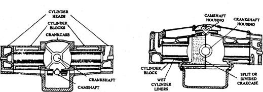
Fig. 3.3. Horizontally opposed cylinder Fig. 3.4. Horizontally opposed cylinder
with detachable crankcase. with divided crankcase.
V-banked Cylinders.
V-banked cylinders have compact and rigid arrangements and are common in engine of 2.5
liters or above. The angle between banks is generally 60 degrees for four- and six-cylinder
engines, and 90 degrees for eight-cylinder engines. An integral cylinder block and crankcase is
used with this block. In this arrangement a central camshaft actuates the valves in each cylinder
block (Fig. 3.5). However, in some heavy-duty diesel engines a separate crankcase is used with
a separate camshaft for each bank (Fig. 3.6).

Fig. 3.5. Monoblock V cylinder Fig. 3.6. ‘V cylinder block
block and crankcase. with detachable crankcase.
3.1.2.
The Coolant Passages
The coolant passages are cast in the cylinder block. These surround the cylinder walls
circumferentially and lengthwise covering approximately the full depth of the cylinders. The
coolant passages terminate near the bottom of the cylinders, where the cylinder walls merge
with the crankcase. At the top of the cylinder, the coolant passages end either at the level of the
block’s joint face, called as an open deck (Fig. 3.7), or just below the block’s machine face, known
as a closed deck (Fig. 3.8). In the closed deck cylinder block, the vertical drillings, which
communicate with corresponding holes in the cylinder head, provide coolant circulation. A closed
deck has better joint reliability than an open deck. On the other hand, it is easier to cast an
open-deck cylinder block.
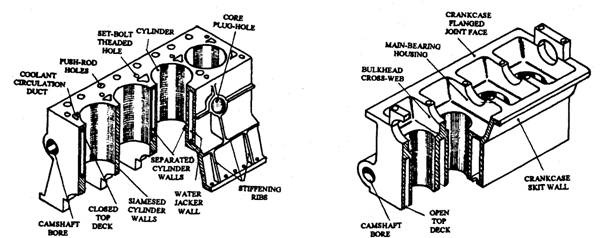
Fig. 3.7. Closed-deck cylinder block. Fig. 3.8. Open-deck cylinder block.
3.1.3.
The Crankcase
The crankcase supports the individual main journals and bearings of the crankshaft and
also maintains the alignment of the journal axes of rotation as they are subjected to rotary and
reciprocating inertia forces and the periodic torque impulses. A tunnel-roof construction of the
crankcase is partitioned-off by bulkhead cross-webs, which mount and support the crankshaft
main journals and bearings (Fig. 3.8). This semicircular ceiling construction with spaced-out
cross-webs offers a very stiff and relatively light crankcase structure.
Over the underslung crankshaft, the crankcase walls from a skirt, which is either separately
attached to the cylinder block’s lower deck (Fig. 3.2) or merged into it as integral casting (Fig.
3.1). The crankcase skirt may enclose the crankshaft from cylinder block to crankshaft-axis level
(Fig. 3.1). However, to provide extra rigidity the walls also extend well below the crankshaft
(Fig. 3.2). This is suitable for both high-performance and heavy-duty engines. Ribs run from the
bottom of the cylinder block diagonally towards the main-bearing housings for additional
support to the cross-webs. In some aluminium-alloy integral cylinder-blocks and crankcases,
stiffening ribs are cast longitudinally and vertically downwards on the outside walls of the block
and crankcase.

Fig. 3.9. V-type engine block. Fig. 3.10. Y-type engine block.
The crankcase walls are flanged at the bottom
to strengthen the casing and to attach the sump.
Two types of lower block designs are in use, name-
ly V-block (Fig. 3.9) and Y-block or deep block :
(Fig. 3.10). The base of V-block is close to the
crankshaft centre. This block is compact and
lightweight. The Y-block improves the stiffness of
the entire engine, which provides smooth and
quite operation, and durability.
3.1.4.
Cylinder Block Material
The cylinder blocks are cast in one piece from
gray iron or iron alloy containing nickel or
chromium for high strength and wear resistance.
Some cylinder blocks are cast from a silicon
aluminium alloy. The cylinder block is a compli-
cated casting. A V-8 cylinder block is illustrated
in Fig. 3.11.
When cast in a monoblock form, the cylinder
block material should have adequate strength
and rigidity in compression, bending, and torsion.
This is necessary to resist the gas pressure loads
and also for the components, which convert the
reciprocating motion of individual piston into a
single rotary motion.
The cylinder-block material should
(a) be relatively cheap,
(b) readily produce castings with good impressions,
(c) be easily machined,
id) be rigid and strong enough in both bending and torsion,
(e) have good abrasion resistance,
(f) have good corrosion resistance,
ig) have high thermal expansion,
(h) have a high thermal conductivity,
(i) retain its strength at high operating temperatures, and
(J) have a relatively low density.
Although cast iron meets most of these requirements, it has a low thermal conductivity and
is comparatively heavier. Due to these limitations, light aluminium alloys have been used as
alternative cylinder-block materials for petrol engines. Cylinder liners (refer section 3.1.5) are
optional with cast-iron blocks; but are more essential with the relatively soft light aluminium
alloy blocks, as they cannot directly withstand wear resistance. Because of the lower strength
of the aluminium alloys, the blocks are cast with thicker sections and additional support ribs,
so that their weight becomes about half of the equivalent cast-iron blocks.
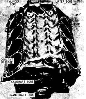
Fig. 3.11. A V-8 engine block.
A typical cast iron is a gray cast iron, which contains 3.5% carbon, 2.25% silicon, 0.65%
manganese, and the balance (93.6%) iron. The carbon improves lubrication property of graphite,
the silicon controls the formation of a laminated structure, called pearlite, which has good wear
resistance, and the manganese strengthens and toughens the iron structure. A common
aluminium alloy composition is 11.5% silicon, 0.5% manganese, and 0.4% magnesium, with the
balance (87.6%) aluminium. The high silicon content in this alloy reduces expansion but
improves cast-ability, strength, and abrasion resistance, while the other two elements
strengthen the aluminium structure. While this alloy provides a good corrosion resistance, it
can absorb only moderate shock loads.
Advantages of cast iron cylinder blocks are;
(i) Good casting properties.
(ii) Free graphite helps to give good wearing properties. The cylinder bore, for example,
can be machined directly in cast iron.
(Hi) Good sound damping properties.
(iv) Tapped holes (i.e., cylinder head studs) are less easily stripped than with aluminium.
Advantages of aluminium cylinder blocks are ;
(i) Lighter in weight.
(ii) Attractive appearance.
(Hi) Easier machining during production.
(iv) Better heat dissipation.
3.1.5.
Cylinder Liner
The liner increases cylinder bore life, as this can be made of an iron suitable more for its
wearing properties than for its casting properties. A single grade of cast iron used to cast cylinder
block cannot have all the optimum individual mechanical properties such as strength, tough-
ness, hardness, and corrosion and wear resistance. Separate cylinder liners are therefore used.
These provide prolonged cylinder life, which outweighs the extra cost. The liners can be made
from lightly alloyed cast iron. They are centrifugally cast into the cylindrical sleeve, machined,
the then heat-treated to produce the optimum wear-resisting properties.
These liners are of two classes :
(i) Those, which are in direct contact with the cylinder bore walls of the cylinder block,
are known as dry liners.
(ii) Those, which are supported only at each end in the cylinder block and are elsewhere
in direct contact with the engine coolant, are known as wet liners.
Dry Liners.
Normally dry cylinder liners (Fig. 3.12) are provided under the following circumstances :
(a) When the cylinder block is made from aluminium alloy, the cylinder bore wall should
be stronger and of much harder wear resistant material.
(b) For heavy duty operating conditions, the normal wear resistance of a cast-iron cylinder
block can be improved through sleeves with superior properties.
(c) When the cylinder block is designed with siamesed adjacent cylinder bores in order to
reduce the over all length, then only dry liners are suitable.
(d) When a cylinder block has been rebored two or three times, then dry liners are used
to restore to the original size of the cylinder bore.
(e) If both bending and torsional rigidities are of concern, a cylinder block with cast-in
coolant passages and cylinder bores fitted with dry liners is more suitable than a block
using wet liners.
The three basic fits used with dry liners are (i) cast-in fit, (ii) force (press) fit, and (Hi) slip
fit.
(i) Cast-in-fit Liner.
For using dry cylinder liners in aluminium-alloy cylinder blocks, the
outside cylindrical surface of the liner is machined to form a helical groove running from top to
bottom. The liners are generally preheated to 473 K and are then placed correctly in the
cylinder-block casting dies before casting starts. This forms a strong metallic bond between the
aluminium-alloy block and the cast-iron sleeve after solidification.
(ii) Force-fit (Press-fit) Liner.
This liner (Fig. 3.12A) is a plain cylindrical sleeve. The
liner is positioned by drawing or pushing the sleeve into the cylinder block with force. This
operation requires suitable end-plates and guides, and either a screw-and-nut draw-bar attach-
ment or a hydraulic-press set-up. Typical interference fits between the sleeve and cast-iron
cylinder block are 0.050 mm and 0.075 mm for bore diameters of 75 to 100 mm and 100 to 150
mm respectively.
(ill) Slip-fit Liner.
This liner (Fig. 3.12B) is a cylindrical sleeve, flanged at one end for
positioning and securing in its location. There is little or no contact between the liner and the
block walls. The liner is inserted by hand pressure. The flange projects above the block face by
0.05 to 0.125 mm to prevent vertical movement relative to the block while in use.
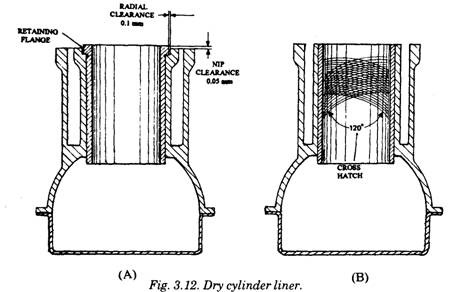
A. Plain force-fit- B. Flanged slip-fit.
Dry Liner Installation.
First the cylinder walls and their counter-bores are cleaned of
rust, carbon, and any burrs. Then diametrical distortion is checked with a micrometer or any
other similar instrument. For fitting the slip-fit liner, the matching between the flange and the
recess bore is checked by blueing the sleeve top face, upturning the sleeve, and rubbing it against
the counterbore face. The sleeve bore is checked for ovalness with a micrometer at two locations
at right angles to each other at the top, middle, and bottom of the sleeve. If the difference at any
of the locations checked exceeds 0.05 mm, the sleeve is rotated through 90 degrees in the cylinder
block and rechecked until the best position is obtained.
During boring out the cylinder block to take the sleeve or re-boring a cylinder block, the
same care for alignment, circularity, straightness, diameter, and surface finish is necessary.
The working tolerance for boring cylinder blocks is +0.0000 to 0.0125 mm.
Due to relatively thin walls the dry liners take up the contour of the finished wall profile.
‘ air pockets are formed by ridge marks from a rough single-point cutting tool, local hot spots
re produced causing distortion, rapid wear and even piston seizure.
Force-fit dry liners are normally supplied with an unfinished internal-bore diameter with
an allowance of between 0.35 mm and 0.50 mm. This allowance is removed by boring and honing
processes after the liners are installed in their respective cylinder-block bore holes. Slip-fit dry
liners may be supplied either as semi-pre-finished liners with an internal-bore allowance of
0.025 to 0.10 mm, which is removed by honing after fitting or as pre-finished liners with no
internal-bore allowance.
The liner bore surface is honed to an accuracy of 0.6 to 0.8 um centre-line (average) with a
Crosshatch angle of 120 degrees (Fig. 2.12A). This provides an optimum oil-retaining surface for
running in new piston rings and cylinder bores (ring bedding). This is required for both
gas-sealing and oil control.
Wet Liners.
Wet cylinder liners (Fig. 3.13) provide the following advantages if used in petrol engines
with aluminium alloy cylinder block having a high coefficient of expansion.
(a) Due to isolation of the bulk of the sleeve from the block, difficult expansion problems
can be resolved at one or two locations only.
(6) The use of wet liners simplifies the casting of the cylinder block. Also, castings of
suitable material can be used with an appropriate heat treatment for structural
requirements, rather than the cylinder-bore wear-resistance treatments.
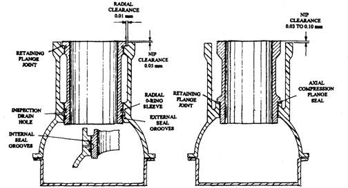
(A) Fig. 3.13. Wet cylinder liners. (B)
A. Single sleeve support with open-deck. B. Double sleeve support with closed-deck.
(c) With better outside surface finish and constant wall thickness the liner improves the
thermal conductance and uniformity of cylinder cooling.
The wet liner is more rigid than a dry liner as the normal cylinder wall is eliminated in this
case. Wet liners fit into the cylinder block at the top and near the bottom, and the remaining
portion of the sleeve is unsupported. O-rings are used to prevent leakage of the coolant. Some
wet liner sleeves have a flange at the top, which sits into a recess machined in the upper deck
of the block. Sometimes a soft copper-asbestos or composite gasket is fitted between the flangf
and the block recess. To hold in position, the sleeve flange protrudes above the block’s top joir
face by 0.05 mm for bores up to 100 mm diameter and by 0.175 mm for cylinder diamete:
ranging from 100 to 150 mm.
The liner is sealed at the bottom by one or more rubber O-rings, usually fitted in grooves
(Fig. 3.13 A). Sometimes an inspection drain hole as shown in the figure is provided in the side
of the block between the seals, to check any leakage through the seals. In another wet
liner-sleeve arrangement, only the lower crankcase end of the liner is supported, which is
flanged to have contact with the corresponding machined face in the block. A flat gasket is used
between these two joint faces (Fig. 3.13B). Since the top of the liner sleeve has no side support,
it depends totally on vertical compression of the liner caused by the cylinder head and gasket
during tightening down. For correct compressive support, the liner’s top face projects above the
cylinder block’s deck by 0.03 to 0.10 mm, depending on the diameter of the cylinder bore, and
the tightening-down torque.
Wet Liner Installation.
The old gasket or/and sealing rings are removed and the portion
of the block that comes into contact with the liner is cleaned using a scraper and emery cloth.
The new liner is inserted into the block without sealing rings or gaskets. It is turned by hand
to find out if there is any tightness, which could cause distortion of the sleeve. The liner flange
must be smooth and square in the counter bore, otherwise the flange might break off while
tightening the cylinder head. Any burrs or dirt that might lift the flange is removed. The
projection of the liner flange above the block face is measured to ensure an adequate clamping
interface.
The seating rings are then fitted without overstretching or twisting them. A coating of
sealing compound may be applied and the liner sleeve is guided into place by hand, followed by
lightly tapping with a soft hammer. At this stage, the sleeve cylinder bore is checked for any
misalignment or distortion.
Liner Materials.
Some commonly used liner materials are nitrided steels, nitrided cast irons, and heat treated
chromium and other alloy cast irons. The wear resistance of these metals is at least 50% more
than the cylinder block material. The typical specification of liner material is :
Iron 93.92 to 92.22%
Carbon 3 to 3.5%
Silicon 1.8 to 2.4%
Manganese 0.5 to 0.8%
Phosphorous 0.4 to 0.7%
Sulphur 0.08%)
Chromium 0.3%
3.1.6.
Gaskets
Gaskets or static seals are used between attaching engine parts to seal the joints for
preventing either internal or external leakage. A gasket must withstand the high pressure and
temperature of the engine. Therefore, the gasket
(i) must be impermeable to the fluids in contact,
(ii) must conform to any existing surface imperfections,
(Hi) must be resilient to maintain sealing pressure, even when the joints are slightly
loosened as a result of temperature changes or vibration,
(iv) must be resistant to all expected changes in its environment due to temperature,
pressure variations, and age, and
(v) must be stable under compression conditions, avoiding excessive setting.
The essential considerations of a gasket are
(a) adequate shear and tensile strengths, particularly for use with narrow sections,
(b) adequate provision for the cooling of the mating surfaces specifically the cylinder head
and for minimizing the effect of differential thermal expansion,
(c) maintenance of a gasket-thickness tolerance, and
(d) a gasket of simple construction, easy to assemble, and not readily damaged.
The gasket thickness and hardness must be chosen to match the degree of unevenness of
either joint face due to large tolerances, distortion, surface roughness, or other factors such as
lack of uniformity of bolt or stud loading. The following gaskets are commonly used in automobile
engines.
(a) Copper-asbestos gasket.
(b) Steel-asbestos gasket.
(c) Steel-asbestos-copper gasket.
(d) Single steel ridged or corrugated gasket.
(e) Stainless steel gasket.
(f) Asbestos-coated steel sheet with separate steel beading around bore.
(g) Laminated steel and graphitized asbestos sheet with formed steel bore bead.
(h) Asbestos impregnated rubber bonded with reinforced ferrule bead.
(i) Asbestos/steel wire-reinforced tissue.
The material used for gaskets depends on the sealing requirement and cost. Cork, one of
the oldest gasket materials, has limited use only to lightly loaded joints having uneven surfaces
such as rocker covers and oil pans. Aluminium coatings on cork gaskets help reduce heat
deterioration. In some cases cork gaskets are rubber coated. Cork gaskets are often replaced by
gaskets made of fibers such as cellulose, asbestos, or a mixture of two. Gasket fibers are bonded
together with a binder, and the binder is impermeable to oil in some cases and other cases it
swells on contact with oil, depending upon the use. Fiber gaskets require a better parting surface
smoothness than is needed by cork gaskets.
Molded oil-resistant synthetic rubber is often used where the sealing requirements dictate
special seal designs such as oil pan corner joints and intake manifold ends. A new approach to
gaskets is a plastic gasket material in a tube used in place of paper and fiber-based gaskets.
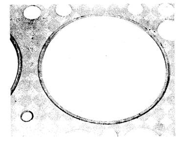
Fig. 3.14. Head gasket with a fire ring.
Sealing of the cylinder head at
the block parting surface is one of the
most difficult sealing jobs. Earlier
head gaskets were copper-coated as-
bestos. As engine design improved,
copper on the gaskets was replaced
by steel to withstand the higher
pressures and temperatures. Steel
rings, called fire rings, were applied
to the gaskets around the cylinder
openings to seal the combustion
chambers (Fig. 3.14).
A more recent head gasket
development uses a thin steel core
with a thin coating of asbestos rolled
on the outside. This provides the gas-
ket the desired resilient properties
needed to withstand the head and
block temperature changes and the
pressure variations within each
cycle. Most head gaskets must be
installed in a specified direction because the gasket is often used to help control engine coolant
flow. When this is required the gasket is marked top or front. Head gasket types are shown in
Fig. 3.15A,Band C.
Timing cover gaskets are usually made of thin fiber or paper. Cork, fiber and synthetic
rubber are used in different parts of the oil pan. The intake manifold uses embossed steel or
reinforced fiber gaskets. Cork or synthetic rubber sections are used on the lifter valley cover
portion of the intake manifold. After use, a gasket loses most of its sealing properties. It is
common practice to use a new gasket each time a part is assembled. Often, the gaskets are
coated with a special varnish, which
melts and seals all the smaller inter-
sticks between the meeting surfaces
when the engine warms up.
3.1.7.
Cylinder Block Attachments
A number of parts are attached to
the engine to enclose it and to adapt it
to the vehicle. These include covers,
housings, and mounts.
Bell Housings.
A bell housing enclosing the
flywheel and clutch or torque con-
verter is attached to the rear of the
cylinder block. It is positioned with
dowel pins for alignment. Offset
dowels and shims between the block
and bell housing may be used to align
the bell housing in standard transmis-
sion applications, so that the clutch shaft matches the pilot bearing. Alignment of the automatic
transmission is simplified by using a flex plate transmission drive. Most automatic transmission
cases from the bell housing, while standard transmission have separate bell housings with cluth
lever attachments. Aluminium bell housings are normally used in passenger cars to minimize
weight.
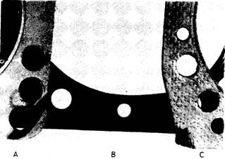
Fig. 3.15. Types of head gaskets.
A. With metal outside the asbestos.
B. Steel embossed.
C. Steel core with outside coating of asbestos.
Timing Covers.
The simplest timing covers are made of stamped steel or cast steel (Fig. 3.16A and B) and
attached with cap screws. Its only purpose is to protect the gears from foreign objects and to
keep the engine oil in. A cast cover also tends to muffle the timing drive noise. Some timing
covers are die-cast. The die-cast process produces an almost finished cover at extra tooling cost,
which balances the savings made in machining costs. In some designs the timing cover is made
more complicated (Fig. 3.16C) by including the oil pump and distribution drive along with the
fuel pump and water pump. With this type of cover, the block contains no accessory drives.
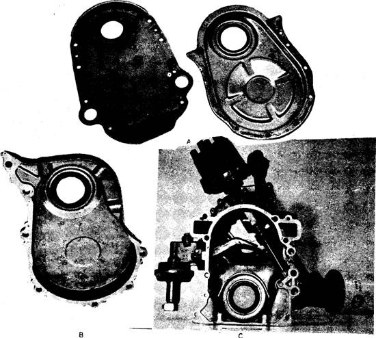
Fig. 3.16. Timing covers.
A. Stamped steel- B. Cast steel.
C. Cast with fuel pump, water pump, oil pump, and distributor attachments.
Engine Mount.
Engines are mounted on the chassis through rubber insulators. The engine mounts are
positioned close to vibration nodes, which are points of minimum vibra tion. The rubber used
in engine mounts is especially compounded to absorb vibrations, characteristic to each specific
engine model. The mounts are usually located about half way back on each side of the block.
The latest mounts (Fig. 3.17B) hold the engine even if the damper rubber breaks, in contrast to
earlier mounts (Fig. 3.17A).
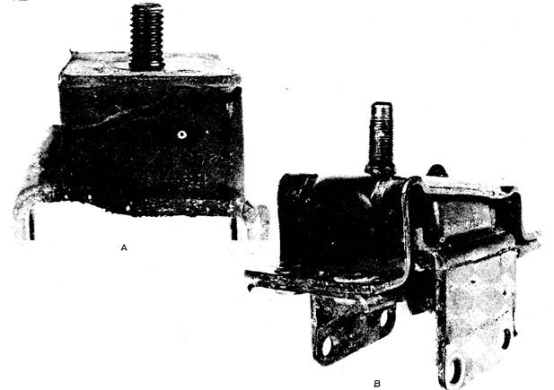
Fig. 3.17. Engine mounts.
A. Old style.
B. New style.
