17.5.
Crankcase Emission Control
The problem of crankcase ventilation is encountered since the beginning of the automobile because no piston ring, new or old, can have a perfect seal between the piston and the cylinder wall. During running of the engine, the pressure of combustion forces the piston downward, and also the chamber gases past the piston rings and into the crankcase. These outlets are called crankcase vapours, or blow by.
Crankcase vapours contains light hydrocarbons, crankcase oil vapours, and combustion chamber gases. Crankcase oil vapours constitute the light volatile portions of the motor oil, evaporated at engine operating temperature. Combustion chamber gases, which have entered into the crankcase primarily come from the quench area within 0.05 mm to 0.5 mm of the combustion chamber surface. These gases have the same olefinic content as the gasoline being used. These gases are unburnt because they are cooled by the relatively low-temperature of combustion chamber wall surface. Every time a driver opens the throttle, the rate of flow of blow-by gases to crankcase increases. The blow by gas causes three undesirable problems.
(i) It destroys the lubricating properties of engine oil.
(ii) It allows to form sludge and varnish.
(Hi) It helps to form corrosive acids, which damage engine parts.
17.5.1.
Draft Tube Ventilation
Ventilation of the crankcase is necessary to remove these vapours and gases. After studying
various possibilities of ventilating the engine crankcase, car makers initially adapted the road
draft tube (Fig. 17.4). This is simply a tube connected to
the engine crankcase for release of vapours into air.
Fresh air enters into the crankcase and mixes with the
vapours to ventilate the crankcase. When the car moves,
a vacuum is developed by the airflow past the road draft
tube. This vacuum draws the crankcase vapour out into
the atmosphere. However, the road draft tube has three
major shortcomings.
(i) To work better it requires a pressure difference between the oil filter cap and the draft tube. This pressure difference depends on car movement. When the car speed is less than about 40 kmph, enough vacuum is not available to remove the vapours from the crankcase.

Fig. 17.4. Road draft tube ventilation.
(ii) It allows the crankcase vapours to directly pass into the atmosphere causing further pollution.
(Hi) At higher vehicle speeds, not only crankcase ventilation accelerates but also engine oil consumption increases because oil droplets are drawn out through the road draft tube.
17.5.2.
Positive Crankcase Ventilation (PCV) Systems
To overcome the drawbacks of the road draft tube, the controlled or positive crankcase ventilation system was introduced, which works on intake manifold vacuum to draw the vapours from the crankcase into the intake manifold. This gives rise to a positive movement of air through the crankcase whenever the engine is running so that the vapours are drawn into the combustion chambers, through intake manifold where they are burned. Depending upon the design, the PCV systems may be open or closed type.
17.5.3.
Open PCV Systems
Positive crankcase ventilation was first introduced on 1961 California cars and were installed in a large scale nationwide on 1963 models. Open PCV systems only partly control crankcase emissions, because manifold vacuum decreases considerably under heavy load or acceleration. This causes the crankcase pressures to build up, so that some of the vapours are forced into the atmosphere through the vented oil filler cap. If the system becomes clogged, crankcase vapours also pass through the vented cap into the air. However open PCV systems promote longer engine life by removing most harmful vapours from the crankcase, and reduce the amount of crankcase vapours, which pollute the air in comparison to draft tube ventilation. Open crankcase ventilation systems can be divided into three types.
Type I System. In this system, a hose connects the crankcase to the intake manifold (Fig. 17.5). When the engine is running, fresh air is drawn into the crankcase through the vented oil filler cap. This air mixes with the crankcase vapours, travels to the intake manifold, and is drawn into the engine cylinders. A PCV valve (Fig. 17.6) regulates airflow from the crankcase. The value has a spring-operated plunger that responds to spring force and manifold vacuum to regulate the air flow.
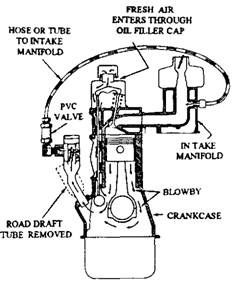
Fig. 17.5. Type I open PCV system.

Fig. 17.6. Type I PCV Valve.
Type II System. The type II system is similar to the type I system, except that it uses a diaphragm-type PCV valve and oil filler cap. The PCV valve regulates the airflow according to crankcase vacuum. When vacuum exists in the crankcase, the valve is closed (Fig. 17.7) and flow of vapour takes place through the idle groove. When the crankcase is under pressure (Fig. 17.8) the valve opens and the flow rate through the valve depends on the amount of blow by created by the engine. The oil filler cap has an orifice, which allows the correct amount of air to enter but can not maintain crankcase vacuum. The orifice must remain open at all times for the system to work correctly.
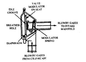
Fig. 17.7. At engine idle, the Type II PCV valve is closed.
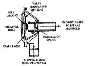
Fig. 17.8. At engine cruising speed, the Type II PCV valve is opened by crank case pressure.
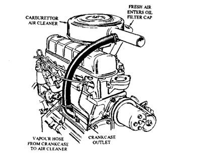
Fig. 17.9. Type III open PCV system has no PCV valve.
Type III System. In the Type III system, the crankcase is connected to the air cleaner by a hose (Fig. 17.9). A slight suction in the air cleaner draws vapours from the crankcase. Fresh
air enters through the oil filler cap, mixes with the crankcase vapours, and is drawn to the air cleaner. From the air cleaner, the vapours are then drawn through the carburettor into the cylinders. Control valve is not necessary in this system.
This system tends to richen the air-fuel mixture, because blow by reaches the carburettor before the mixture is vaporised. Carburettors used with a Type III system must be adjusted to account for this richer mixture. Some cars also use a “sealed” Type III system in which the oil filler cap has no venting hole.
17.5.4.
Closed PCV Systems
Closed, or Type rV, PCV systems were first installed in 1964 on all new California passenger cars. They became standard system for all cars by 1968, and are still in use on cars. In this system (Fig. 17.10), the oil filler cap is not vented to the atmosphere. Air for the crankcase is drawn through a hose from the air cleaner to one of the valve covers or to a crankcase inlet below the intake manifold. The dipstick is also sealed to prevent air leakage into the crankcase.
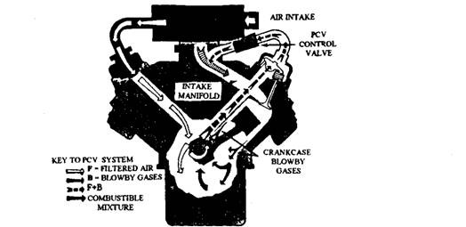
Fig. 17.10. Type IV PCV System.
Crankcase ventilation air may be supplied from either the clean side (inside) or the dirty side (outside) of the carburettor air filter. When air is coming from the clean side using the air cleaner as a PCV filter, a flame arrester (Fig. 17.11) is used. The arrester uses a wire screen installed in the PCV air intake line, either at the air cleaner or at the valve cover, to prevent a crankcase explosion caused due to the engine back fire. When air is coming from the dirty side of the cleaner, a separate PCV air flow is used. This can be located in the air cleaner (Fig.
17.12A), or in the oil filter cap (Fig. 17.12B) or in the inlet air hose where it connects to the valve cover. A flame arrester is not required in this case, since the air cleaner filter serves the purpose.
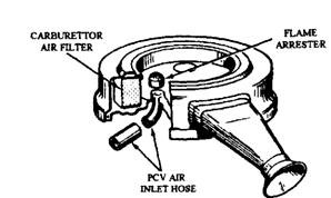
Fig. 17.11. Use of a flame arrester.
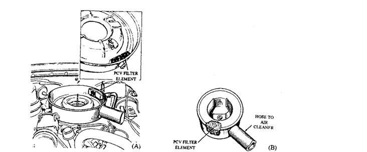
Fig. 17.12. PCV Air filter. A. Located in the air cleaner housing. B. Located in the oil filter cap.
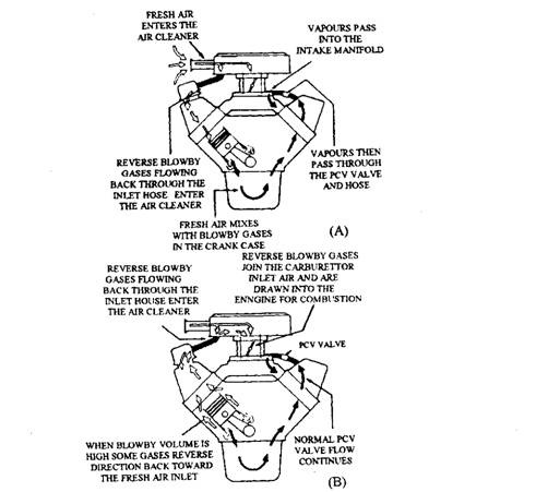
Fig. 17.13. Closed PCV system operation. A. Under normal conditions. B. Under heavy load.
Under normal operating conditions, fresh air from the air cleaner passes through the inlet hose to the crankcase (Fig. 17.13A). The fresh air mixes with the crankcase vapours, and passes through a PCV valve prior to being drawn into the intake manifold. Vapours that back up under certain conditions cannot escape from the closed crankcase ventilation system. If manifold vacuum drops, or if the system becomes clogged, extra crankcase vapours reverse their direction. Instead of passing into the atmosphere, these excess vapours from the engine flow back to the air cleaner (Fig. 17.13B) in the closed system. The vapours in the air cleaner mix with incoming air and pass through the carburettor to the combustion chamber for burning. This allows the closed system to be almost 100 percent effective in controlling crankcase emissions.
Closed PVC system offers the following three advantages :
(i) It improves engine life by removing harmful vapours from the crankcase.
(ii) It eliminates crankcase vapours that cause air pollution.
iiii) It increases fuel economy by recirculating all unburned blow by back to the intake manifold.
17.5.5.
Components of Closed PCV Systems
The design of all types of closed PCV systems is the same and all operate in the same manner (Fig. 17.14), irrespective of the model. All have a PCV valve, an air inlet filter, and connecting hoses. The location of these parts, however, may vary from one engine model to another.
Air Inlet Filter.
PCV air inlet filters are normally installed in a retainer inside the air cleaner (Fig. 17.12A), or in the oil filler cap (Fig. 17.12B). They use wire gauze or polyurethane foam and are normally replaced along with the air cleaner filter element.
Connecting Hoses.
The closed PCV system uses two connecting hoses (Fig. 17.14). Fresh air flows from the air cleaner to the engine through the air inlet hose. Crankcase vapours flow from the engine to the intake manifold through the manifold vacuum hose. PCV hoses are made of special materials that are not contaminated with oil vapours. Heater hose should not be used as a substitute.
PCVValve.
This is a one-way valve having a spring-operated plunger (Fig. 17.15), to control flow rate. Spring force, crankcase pressure, and manifold vacuum together regulate the flow. Flow rate through the valve is set for a particular engine, and hence should not be used in an another engine. This setting is obtained by the size of the plunger and the holes inside the valve. PCV valves are usually installed either in the valve cover (Fig. 17.14) or in the intake manifold (Fig. 17.16).
When manifold vacuum is high, the PCV valve balances air-fuel mixture ratio by regulating the airflow (Fig. 17.17A). It also restricts high intake manifold vacuum only to prevent oil pulling out of the crankcase into the intake manifold. The PCV valve controls the airflow through the crankcase under all operating conditions and speeds. Under high speed or heavy loads, the valve
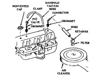
Fig. 17.14. Late-model closed PCV system.
opens to allow maximum airflow (Fig. 17.17B). If the engine backfires, the valve closes instantly (Fig. 17.18) to prevent a crankcase explosion.
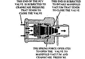
Fig. 17.15. PCV valve flow rate regulation.
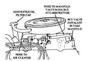
Fig. 17.16. V-8 PCV system installation.
17.5.6.
PCV System Service
A restricted or clogged PCV system, a common problem, is usually due to an engine problem or the lack of proper maintenance. Scored cylinder walls or badly worn rings and pistons permit more blows by to pass. Start-and-stop driving requires more maintenance and causes frequent PCV problems than highway driving, as more raw fuel reaches the crankcase. Using the oil of wrong grade, or not changing the crankcase oil at periodic intervals also causes clogging of the ventilation system.
When clogging starts in a PCV system, the engine tends to stall, idle roughly, or overheat. Due to more restricted ventilation, burned plugs or valves, bearing failure, or scuffed pistons can result. Also an oil-soaked distributor or points, or leaking out around valve covers or other gaskets may occur. Do not overlook the PCV system while trouble shooting. A partly or completely clogged PCV valve or one of the incorrect capacities may cause poor engine performance.

Fig. 17.17. PCV valve air-flow. A. Cruising and light-load operation.
B. Acceleration and heavy-load operation.
