12.7.
Cooling System Maintenance and Service
12.7.1.
Coolant Changes
The coolant has limited life.
Dilution of the antifreeze and depletion of the corrosion inhibitors are the two major changes occur in the coolant requiring replacement. Most automobile manufacturers recommend a coolant change every two or three years. Some even recommend yearly change of coolant. The corrosion inhibitors react to some types of water, oxygen/air, and metal in the system. Leakage of combustion/exhaust gases, increased aeration, excessively high temperatures, rust or corrosion particles, and/or oil leakage into the coolant greatly shorten the life of the inhibitors. To ascertain the quality of the coolant, a sample of the same is tested for its pH value, reserve alkalinity, specific gravity and freezing point, and for metallic and non-metallic elements (spetrochemical analysis).
The antifreeze concentration is diluted every time water is added to make up for coolant loss. This, off course, results in a loss of antifreeze. When there is no coolant loss, there is no need to add water and the freeze protection then lasts for the entire life of the coolant. Freeze and corrosion protection should be maintained by filling a system, if required, with a 50-50 mix of antifreeze and water instead of plain water. Loss of antifreeze can be easily checked by measuring the freezing point of the coolant. If the freezing point is still 236.4 K, the concentration is 50 percent. The different tests used to measure freezing point of the coolant are (a) antifreeze hydrometer (6) ball-type hydrometer and (c) hydrospy/refractory tester.
If there is no indication of rust or corrosion in the system, the coolant can be changed by merely draining out the old and replacing with new. The coolant might appear dirty or rusty, which can be ascertained by running the finger around the inside of the radiator filler neck. A dirty, rusty, and/or oily deposit on the finger indicates the need for a thorough flush, which can be affected either through chemical or mechanical cleaning depending upon the condition.
To drain the system, the radiator drain petcock/plug is opened. The radiator cap is left in place during the first stage of draining and this causes a flow from the coolant recovery tank. If no flow occurs, a faulty cap or a system leak is indicated.
After the recovery tank is empty, the radiator cap is removed. Once the coolant has been drained out, the plugs are replaced, the petcock is closed and the hose installed. Then the system is filled with measured quantity of coolant with 50 percent concentration of antifreeze. Care has to be taken for complete filling of the system otherwise overheating of the engine takes place. The block fills slowly, if it has been drained, while air leaves the block through the small bleed hole/notch in the thermostat.
12.7.2.
Drive Belt Service
Normally the drive belt is replaced when it fails, but it is advisable to replace the belt at regular intervals, every four or five years, and to inspect it at least once a year against wear or damage. Common belt problems are ;
(a) Oil or grease on the belt cause softening and deterioration of rubber due to which eventual slippage and separation occur.
(b) A tensile break or belt separation takes place when the belt wears out. It can also be due to mismatch of belt in the pulley groove, forcing the belt on to the pulley during installation, and a foreign object getting between the belt and pulley during operation.
(c) Glazing/slip burn is the result of belt slippage. Heat generated by belt slippage hardens the rubber. The rubber hardens at the point where it losses its flexibility and at this point cracks often occur. Belt wear often causes reduced tension which increases the slippage and wear.
(d) Worn belt sides are caused by a rough or bent pulley or pulley misalignment. Inspect the pulley grooves to make sure they are smooth, even and aligned.

Belt Tension.
Belt should be checked for proper tension. This can be checked by rotating the alternator pulley using the pressure of one finger. Excessive belt whip/flopping during running is also the indication of belt losseness. Belt tension can be measured by using a Boroughs-type gauge (Fig. 12.35) or a Gates “krikit” gauge. Also in the simplest way belt tension can be measured by deflection (Fig. 12.36).
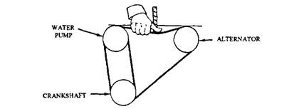
Fig. 12.36. Measuring belt tension by deflection.
Belt Replacement.
In order to remove and replace a vee-belt, the driven component (alternator, A/C compressor, power steering pump, etc.) or idler is located, which is mounted using a pivot and adjusting bolts (Fig. 12.37). The mounting and pivot bolts are loosen. The component/idler is moved toward the engine to the “loosest belt” position. This is often done by giving a sharp outward jerk. A pry bar or hammer handle may be used to move it inward.
The new belt is put into position in the pulley grooves. The components/idler is pulled outward until the belt is tight. It should be insured that the belt fits into all of the pulley grooves. Components with strong housings can be moved by prying directly against the housing (Fig. 12.38). Some components have a square hole in the mounting bracket in which a socket handle can be inserted to gain leverage. A belt

Fig. 12.37. Illustration shows the pivot screws (2 nos) and the locking screws (3 nos) are used to adjust the drive belts.
tensioner can be positioned between two pulleys and adjusted to gain the correct tension. When the belt is at the correct tension, the pivot and adjusting bolts are tightened.
The correct tension varies with the width of the belt and what it is driving. Most car manufacturers provide the belt specifications in their shop manuals. After the belt is replaced, the engine is run at various speeds for three to five minutes. While running the belt is checked for excessive whipping or misalignment. It is a good practice to recheck the tension and readjust it if necessary. When replacing a belt in a double-belt set, it is highly recommended that both belts be replaced at the same time, otherwise the new belt carries most of the load.
Removal or replacement of a multi-vee or serpentine belt is done much like the operations on a standard belt. Spring-loaded tensioners are used to provide correct amount of tension. Tension is loosened to allow belt removal and after replacement of the belt tension is returned. The tensioner pressure is released by prying the tensioner with either a bar or socket handle, depending on the configuration of the tensioner (Fig. 12.39). When a belt is replaced, it is checked to insure that the belt vees are in the correct grooves.
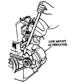
Fig. 12.38. Use of a pry bar for belt tightening.
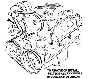
Fig. 12.39. Multi-vee/serpentine belt removal.
12.7.3
Radiator Hose Service
Similar to the drive belt, the hose is usually replaced when it fails. It is recommended to replace the hoses once in every four to five years and inspect them once in every year. The hose should be inspected for cuts, chafing, or abrasion damage which extends into the reinforcing cords or wires. The hoses should be checked for swelling of rubber. Spongy ends or a swollen hose indicates oil or grease damage. The debris from a flaking hose usually causes plugging of the tubes in the radiator. If the hose is too hard, than it should be observed for cracks, which indicates that the hose is becoming brittle. Faulty or suspicious hoses should be replaced. Even a squeezed lower hose must be replaced.
Removing a Hose.
The hose usually sticks to the inlet/outlet connection. If excessive force in pulling and twisting the hose is exerted, it can damage the connection and/or radiator or heater core. The safest and simplest way to remove the hose is to cut it off with a sharp knife. If the hose is to be re-used, it can be loosened by inserting a small cotter pin puller or screw driver between the hose and the connection. The tool should be used carefully around the inside of the hose until the hose can be twisted and slid off.
Hose Replacement.
When a corrosion build-up is observed, the inletfoutlet connection is to be cleaned with a wire brush or coarse sand paper. The hose clamp should be positioned about 6 to 12 mm from the end of the hose, and the clamp should end up just past the ridge on the connection (Fig. 12.40). When the clamp is placed in this position, it insures that the hose does not blown off and
also reduces the area for corrosion outside of the flange to a minimum. The clamp is turned such that it is easily reached with a screw driver and then it is tightened. The correct torque for a worm drive, type F camp is 4.5 to 5.5 Nm. If no torque wrench is available, the hose clamp is tightened until the rubber begins squeezing up into the slots in the clamp.
After the hose have been replaced, the cooling
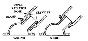
Fig. 12.40. Placing the hose clamp.
system is refilled, the cap is replaced and the engine is started. When the engine reaches the operating temperature, the hoses are checked for leaks. It is a good practice to retighten the hose clamps after the engine has warmed up and then cooled down. It is because the expansion and contraction often cause the hose and/or clamp to creep into a more relaxed position.
12.7.4.
Radiator Service
Bugs, leaves, and other roadside airborne debris are normally collected on the core area of the radiator. These materials tend to reduce the air flow through the core and cause overheating. Air borne debris can usually be removed from the front of the core with a spray from a water hose or a blast of air. It is sometimes necessary to remove the radiator to clean the front of the core and the back of the condenser.
Radiator leaks are usually easy to find. Telltale marks, because of the dye in the antifreeze, wet areas, whitish lime deposits or brownish rust, are the indications of a leak. If leaks are found, the radiator should be removed and repaired at a specialty shop.
12.7.5.
Radiator Cap Testing
A faulty radiator cap can release the system’s pressure so that the coolant boils at normal operating temperatures. Also it can allow air to enter the system during cooldown in coolant-recovery-equipment systems.
The cap is removed in the cooled down system. If the radiator is not completely full of coolant and there is coolant in the recovery tank, then either the upper gasket of the cap is faulty, there is a defect in the top of the filler neck, or there is a leak in the cooling system. Also, it is checked for a cut, plugged, or kinked hose between the radiator and the recovery tank.
A faulty lower gasket or defective vacuum valve can cause a cap to loose pressure. In order to check the cap’s ability to hold pressure, the cap is immersed in water to aid in sealing of the lower gasket and then the cap is attached to a radiator cap tester (Fig. 12.41). The tester is pumped while watching the pressure gauge. The pressure should build up to the cap’s pressure rating, usually stamped on the cap and held at that pressure. A faulty cap should be replaced with one of the correct type and pressure rating.
12.7.6.
Water Pump Service
The water pump requires no service in normal operation. Older pumps require lubrication, but recent pumps have sealed bearings which require no lubrication. If the pump develops noise, leaks, or becomes otherwise defective, it is replaced with a new pump. The most common water pump faults are a broken or loose impeller which stops the pumping operation, worn bearings which cause noisy operation with a loose shaft, a faulty seal which causes leaks, and a broken shaft which makes the pulley and fan fall off.
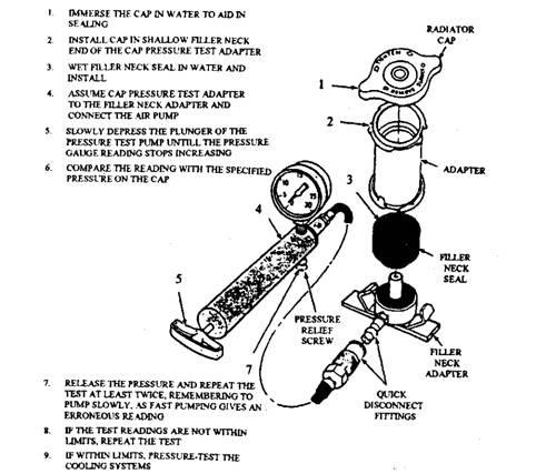
Fig. 12.41. Radiator cap pressure testing.
In normal operation, the impeller blades may wear away, which may result from abrasive action of sand in the cooling system. Rusting of the blades may result from use of old antifreeze without active rust and corrosion inhibitors, or from the use of plain water in the cooling system.
For removing the water pump, the cooling system is drained. The inlet hose and the heater hose from the pump are removed and also the fan belt. The pump is taken off, after removing the attaching bolts.
The procedure for the installation of the pump is the reverse of the removal of the pump. After installation of the pump, the fan belt is checked for tension and then the cooling system is filled with coolant before starting the engine.
12.7.7. Cooling System Pressure Testing
A pressure tester, shown in Fig. 12.42, is used to check the leaks in the cooling system. For pressure testing, the radiator cap is removed and the radiator is
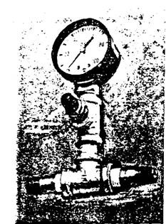
Fig. 12.42. A pressure tester.
filled with the coolant until the level is about 12 mm below the bottom of the filler neck. Then the pressure tester is attached to the neck and the pump is operated to create a pressure within 20 kPa above the manufacturers’ specification. If the pressure holds steady, the system does not have any leak. If the pressure drops, then hose connections, hose, engine expansion plugs, water pump and cylinder head gaskets, water-pump shaft seal, and radiator are to be checked one by one for leaks.
If leaks are not detected with visual inspection, then the engine is started after removing the tester until operating temperature is reached. The tester is reattached and pressure is raised to about 100 kPa and engine speed to about 3000 rpm. If the needle of the pressure gauge fluctuates with engine speed, then it indicates an exhaust gas leak, probably through cylinder head gasket. If the needle does not fluctuate, then there is possibility of a cracked block or head, or a defective gasket. The repair of the leak is to be attended accordingly.
