16.2.
Conventional Ignition Systems
The jump-spark system used today in the internal combustion engine has been gradually developed through the stages of hot wire, break spark trembler coil, with each step showing a
definite improvement over its predecessor. The two jump-spark ignition generator systems in use today are the battery-coil and the magneto, the latter is confined mainly to the small engines used on motor cycles and lawn mowers.
16.2.1.
Coil-ignition System
In 1908 the battery-inductive ignition system was introduced by C.F. Kettering of Delco, but only in the mid 1920s it could achieve its commercial status as a successor to the magneto. Up to that time very few vehicles used a battery, hence the magneto was common being a self-contained ignition generator. With the introduction of electric lighting, use of a battery becomes necessary. Because of this as well as the difficulty in starting of the magneto-ignited engine, the battery inductive system commonly known as coil ignition was introduced.
Conventional Coil-ignition Circuits.
The circuit shown in Fig. 16.1 is for a coil-ignition system with main components. The heart of the system is the ignition coil, which transforms the low-tension (LT), 12 V supply given by the battery to the high-tension (HT) with voltage needed to produce a spark at the spark plug.
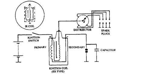
Fig. 16.1. Coil ignition system.
The coil has primary and secondary windings forming two complete circuits that make up the complete system. Primary, the LT circuit, is supplied by the battery and secondary, the HT circuit incorporates the distributor and spark plugs. The end of the secondary winding in the coil is earthed, which is achieved by connecting the winding either to the LT coil terminal (normally the negative) or to an additional coil terminal that is linked by an external cable to earth. The latter arrangement of coil is called an insulated return (IR) coil to distinguish it from the common earth return (ER) type and is needed on a vehicle using IR system.
The contact breaker interrupts the primary DC current to induce the HT voltage into the secondary winding at the instant the spark is required. To obtain the precise timing of the spark the break in the primary circuit is required to be sudden, and to avoid arcing at this critical stage a capacitor is installed ‘across’ the contact breaker.
The operation of a coil-ignition system is based on the principles of mutual induction and the transformer action. When both the ignition switch and contact breaker are closed, a current of about 3 A flows through the primary winding of the coil creating a strong magnetic flux around
the winding. The contact breaker is opened at the appropriate time by a cam driven at the speed of the engine camshaft, i.e. half crankshaft speed. This breakage of the primary circuit causes a sudden collapse of the magnetic flux in the coil and induces an emf into the secondary winding, which has about 60 times as many turns as the primary winding. The transformer action, combined with the effect of the self-induced voltage in the primary, steps-up the voltage to that required to produce a spark at the plug. However, with the increase in the secondary voltage there is a proportional decrease in the current.
The secondary winding is connected to the negative LT coil terminal, due to which the primary and secondary windings are arranged in series. This connection is called the auto-transformer connection, which adds the self-induced emf in the primary to the mutually induced emf in the secondary providing a higher output.
In a single-cylinder engine, a highly insulated lead is used to convey the HT current directly to the spark plug. But, a distributor is necessary in a multi-cylinder engine to allocate the HT current to the appropriate spark plug. The distributor is a HT rotary switch comprising of a distributor and a rotor arm, rotating at camshaft speed. The plug leads are connected to brass electrodes in the cap maintaining the firing order of the cylinders. A lead from the coil tower makes contact with a carbon brush that rubs on a brass blade forming part of the rotor arm. An automatic advance mechanism, installed adjacent to the contactor breaker, alters the timing of the spark to suit the engine speed and load. It alters the spark timing by moving both the cam and the base plate on which the contact breaker is mounted. The unit, called ignition distributor incorporates the distributor, contact breaker and automatic advance mechanism.
16.2.2.
Components of Coil-ignition Ignition Coil.
The ignition coil (Fig. 16.2) is termed a pulse generator as it delivers an HT output only when a spark is required. The coil contains at the centre a laminated iron core around which a secondary winding of about 20,000 turns of thin enameled wire of 0.06 mm diameter is wound. Over this winding is placed the primary winding, which is separated from it by layers of varnished paper. For a 12 V system the primary winding is consisted of about 350 turns of enamel-covered wire of diameter 0.5 mm. The varnished paper is placed between each layer of wire to improve the insulation.
To localise the magnetic flux a slotted iron sheath is placed inside the aluminium case and the winding assembly is separated from the case by a porcelain insulator support and a plastics-moulded, air-sealed cover. LT terminals in the cover are connected to the
ends of the primary winding. The secondary winding is connected to the coil tower which is placed remotely from the LT terminals. This minimizes the risk of the HT current flashing-over to earth or tracking across the cover during presence of moisture.
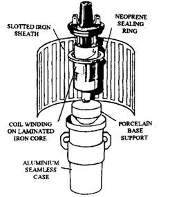
Fig. 16.2. Coil construction.
Flash-over is caused when the voltage required for the HT current to jump-to-earth outside the cylinder is lower than the voltage needed to produce a spark in the cylinder. Tracking occurs when the HT current takes an alternative path to earth over the surface of an insulator instead of sparking at the plug. Tracking burns the surface and leaves a deposit, which acts as a conductor. The insulator surfaces should be nonporous to avoid tracking.
Normally the windings of the coils are immersed in oil. This improves insulation, overcomes the corona effect (faint glow of light around the coil) and reduces moisture problems. Also, the presence of oil improves cooling of the primary winding.
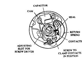
Fig. 16.3. Contact breaker assembly.
Contact Breaker.
The contact breaker is a cam-actuated switch, which triggers the signal when an HT impulse is required for the spark plug. Since the cam revolves at half crankshaft speed, all cylinders are fired in one revolution of the cam. For 4-stroke engine, the numbers of lobes on the cam are same as the number of cylinders. The layout of a contact breaker assembly for a 4-cylinder, 4-stroke engine is shown in Fig. 16.3. The two contacts, or points, are made of tungsten-steel alloy to resist the electrical burning action. One of the contacts is attached to the base plate and the other is fixed to a plastics block that rubs on the cam face. A strip spring of stainless steel pushes the heel of the block firmly on to the cam, holds the contacts closed when the heel is free from the cam lobe and also acts as a conductor for the flow of current.
The cam in the figure is positioned at a point where the contacts are just opening representing the instant when the spark occurs. Further rotation of the cam opens the contacts wider making the gap the greatest; a typical gap is 0.38 mm, which can be checked with a feeler gauge. An alteration to the contact gap changes the sparking timing. A smaller gap causes the cam to strike the contact heel later so the spark is retarded.
After a long service of a contact breaker it is observed that the metal from one contact has vaporised and been transferred to the other contact as shown in Fig. 16.4. The crater normally occurs on the positive side, which is reversed when a smaller capacitor has been used. Electrical burning blackens the contact face forming an oxide, which is resistant to current. When the contacts reach this stage they require replacement.
Various methods are incorporated to overcome the crater and burning problems. One method uses a contact on the positive side, having a hold formed in the centre. Another method uses a sliding contact (Fig. 16.5) where the operational movement of the base plate makes smaller contact to move across the other contact. This wiping action has cleaning effect. This design reduces the pitting of the contact and increases its life to 40,000 Km.

Fig. 16.4. Pitting and piling of contacts.
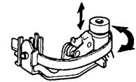
Fig. 16.5. Sliding contact type contact breaker.
Dwell.
The angle formed during the closed-open period is called the phase angle or firing angle and is given by 360/ (number of cylinders). Therefore for a 4-cylinder engine this angle is 90 degrees (Fig. 16.6), a 6-cylider engine has an angle of 60 degrees, and an 8-cylinder 45 degrees.
The dwell angle (or cam angle) is the angle moved by the cam during the contact-closed period. A dwell meter is used to measure the angle more accurately as this method takes the reading during running of the engine. For obtaining correct dwell angle, the contact gap measurement (in mm) should be within the specified limits. However, this does not hold well when the unit
is worn. The increase in contact gap decreases the dwell angle which advances the ignition by a similar amount. For example reducing the dwell angle, from 54 degrees to 51 degrees advances the ignition by 3 degrees. A typical dwell angle for a 4-cylinder engine is 54±5 degrees, i.e. 49-59 degrees. The duel angle depends on the type of distributor and the number of engine cylinders. The affect of dwell on the ignition timing requires that the dwell on each cam lobe should be equal, otherwise due to the timing variation between cylinders the engine runs erratically. The dwell is also stated as percentage dwell where the dwell angle is related to the phase angle and is calculated as:
Percentage dwell = (dwell angle /phase angle) x 100
A dwell angle of 54 degrees for a 4-cylinder engine has a percentage dwell of (54/90 x 100 = ) 60%. This means that the contacts are closed for 60 % and open for 40% during the phase in which the spark for one cylinder is being produced. Contact gap and dwell are interrelated. A larger gap causes the contacts to open earlier, thereby producing a shorter dwell. Therefore, dwell-angle alteration changes the spark timing. A dwell angle change from 54 to 59 degrees causes the spark to occur 5 degrees later.
Capacitor.
The capacitor minimizes arcing and hence speeds up the collapse of the magnetic flux. As the cam is rotated with capacitor disconnected severe arcing takes places at the contacts. If the contacts are opened, an induced emf of over 400 V is generated in the primary circuit, which causes a spark to jump across the contacts as they initially part. Due to the passage of this induced current, in the form of a spark across the contacts, a gradual fall in the primary current takes place instead of a sudden fall. This arcing affects the speed of collapse of the magnetic
flux, and quickly destroys the surface of the contacts.
A capacitor acts as a buffer device in an ignition circuit. The capacitor provides an alternative path for the surge current when the contacts have just parted. Instead of jumping the small contact gap, the current flows into the capacitor charging it up. After a fraction of a second the capacitor discharges, but by this time the contact gap is too wide for the spark to jump across.
The capacitor connected in parallel with the contact breaker and is placed close to the breaker to minimize inductance and resistance of the lead. A cylindrical type

Fig. 16.6. Dwell angle.
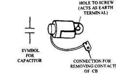
Fig. 16.7. Capacitor.
capacitor is commonly used with a coil-ignition system (Fig. 16.7) and has a typical capacity of about 0.2u F. It uses two rolled up sheets of metallized paper separated from each other by a dielectric insulator. One sheet is joined to the earthed aluminium alloy container and the other to an insulated terminal, attached to a ‘pig tail’.
Automatic Advance Mechanism.
Precise timing of the spark provides maximum power and economy. Incorrect timing of the spark in relation to the piston position gives rise to problems like overheating, pinking, piston damage and exhaust pollution. To overcome these problems the spark timing should allow the maximum cylinder pressure to always occur about 12 degrees after TDC. A certain time elapses between the production of the spark and maximum cylinder pressure. For the particular engine this time depends on the air-fuel ratio and the compression pressure, the latter however is governed by the throttle opening.
Timing the Spark to Suit the Speed. Even if it is possible to time the spark to give the required pressure at the correct instant considering only the pressure and mixture quality, but this timing is only suitable for one particular speed. At a faster speed, the crankshaft moves through a larger angle during the burn time, requiring the spark to occur earlier, that means the ignition has to be advanced.
For the spark advance requirement of the engine in Fig. 16.8A the burn-time is 0.004 second, and hence at 1000 rpm the spark timing is 10 degrees before TDC and maximum pressure is at 12 degrees after TDC. After this speed the total burning period is 22 degrees. Figure 16.8B represents the spark timing for a speed of 2000 rpm. Assuming the burn-time is constant at 0.004 second, the angle moved by the crankshaft and the spark advance is as follows :
| Speed | Angle during burn | Advance from TDC |
| (rpm) | (degrees) | (degrees) |
| 1000 | 22 | 10 |
| 2000 | 44 | 32 |
| 3000 | 66 | 54 |
In practice the burn-time does not remain constant, and taking the variation into account, a spark advance requirement is shown in Fig. 16.8C.
One type of speed sensitive-centrifugal advance mechanism is presented in Fig. 16.9. The basic principle of operation is the same for all other types of construction. The rolling contact type of arrangement shown in the figure uses two flyweights, pivoted to a base plate, which is driven by the distributor spindle. A contoured face on the driving side of each flyweight acts against the cam plate on to which the contact breaker cam is secured. This cam only bears on the drive spindle and is driven through the flyweights. Two tension springs are located between the base plate and the cam plate, which hold the cam plate firmly against the flyweights. The strength of the springs controls the movement of the flyweights relative to the centrifugal force developed at a given speed.
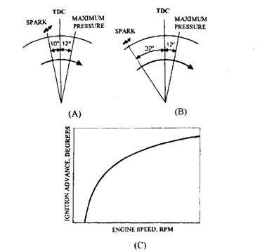
Fig. 16.8. Ignition advance. A. 1000 rpm. B. 2000 rpm. C. Ignition advance requirement.

Fig. 16.9. Speed-sensitive centrifugal advance mechanism.
As the flyweights move outwards with the increase of engine speed, the cam plate is also moved forward in relation to the base plate causing the cam to open the points earlier. This action gives a progressive advance to match the increase in speed until the full travel of the flyweight is reached. Alteration of either the spring strength or the contour of the flyweight changes the angle of advance for a given speed. Figure 16.10 represents the relationship between advance and speed. For a typical mechanical advance mechanism the maximum advance is about 46 crankshaft degrees.
Some advance mechanisms use unequal strength springs as shown in Fig. 16.11. The strong spring is slack on its post while the weaker spring is under tension. The weaker spring only resists outward movement of the flyweights up to an engine speed of about 1000 rpm. Above
this speed both springs work together. This type of construction provides a large rate of advance up to 1000 rpm and a smaller rate of advance beyond this speed.
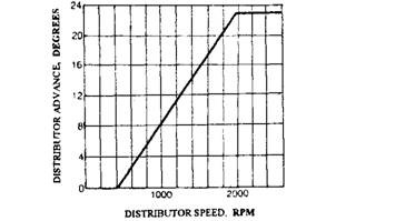
Fig. 16.10. Typical advance provided by centrifugal advance mechanism.

Fig. 16.11. Centrifugal advance unit with springs of unequal strength.
Timing the Spark to Suit the Load. To improve economy some carburettors supply a slightly weak mixture to the engine under light load operation, when the vehicle is ‘cruising1. To compensate for the slow burning of a weak mixture, extra advance of the spark is needed. The depression in the induction manifold varies with the load on the engine. At light load the depression is high and under heavy load, the depression is very low so that the pressure is just below atmospheric. Therefore, the manifold depression is used by the advance mechanism and carburettor to sense the cruise condition. Manifold depression, or the common term ‘vacuum’ (but technically incorrect) operates a spring loaded diaphragm to control the timing of the spark.
A typical vacuum advance unit, capable of giving an advance of about 13 crankshaft degrees, is shown in Fig. 16.12. The diaphragm chamber of this unit is installed on the side of the distributor unit and is connected with the induction manifold through a rubber hose. A small vent of the non-vacuum side of the diaphragm is open to the atmosphere. The diaphragm is connected to the contact-breaker base plate through a linkage. To advance the spark the base plate is moved in a direction opposite to cam rotation, so that the contact breaker heel is moved towards the cam lobe.
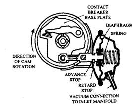
Fig. 16.12. Operation of vacuum control.
The vacuum advance unit should not provide advance during engine idling even though the manifold depression is very high. To achieve this vacuum pipe is connected to the carburettor in the vicinity of the throttle. At idling the throttle is nearly closed, so the manifold depression cannot act on the advance unit (Fig. 16.13).

Fig. 16.13. Vacuum pipe connection. A. Cruising (light load) condition. B. Slow running condition.
At small throttle openings, maximum depression acts on the diaphragm, causing a pressure difference on the diaphragm that moves it against the resistance of the spring and advances the ignition. At other throttle openings, the reduced depression provides an advance to suit the cylinder conditions. At cruising speed, a sudden opening of the throttle immediately destroys the manifold depression. This is desirable because the vacuum advance retards the ignition and counteracts the tendency for the engine to pink under these heavy load conditions. Figure 16.14 shows the advance provided by the vacuum advance unit. The spark delay / sustain valve and the dual-diaphragm unit are the two additions out of the many, introduced on a basic vacuum advance system to meet the exhaust emission regulations.
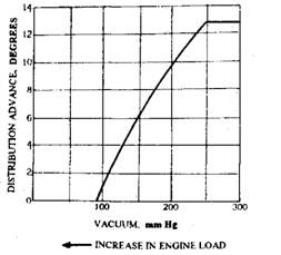
Fig. 16.14. Typical advance given by vacuum advance unit.
Spark Delay/Sustain Valve.
This dual-purpose valve can be installed in one of two ways of suit a given engine. Figure 16.15 diagrammatically shows a oneway valve and a by-pass bleed orifice. The unit is fitted in the rubber pipe between the vacuum advance unit and the carburettor.
When pipe A, shown in the diagram, is joined to the carburettor the device works as a spark delay valve, which improves driveability and reduces emissions by delaying the full ignition advance until the air-fuel mixture has stabilized. On some cars the
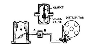
Fig. 16.15. Spark delay valve.
device is called a spark control system. When pipe B is connected to the carburettor the device acts as spark sustain valve, which maintains vacuum advance for a short time after the throttle has been operated. Although the valve has little effect on the performance of a warm engine, but it provides a considerable improvement in driveability when the engine is cold. Thus the valve is fitted to perform in the desired manner.
Duel-diaphragm Vacuum Control.
This control system provides an improvement in exhaust emission as it causes extra retardation during engine deceleration with a closed throttle and also during idling. Emission at the idling speed is improved by setting the throttle to open wider than normal and then dual diaphragm retards the ignition in order to offset the increase in speed. The unit (Fig. 16.16A) uses a second diaphragm to control the stop, which limits the retardation movement of the first diaphragm. Manifold pressure is used to sense the idling condition and for this purpose rubber pipe connects a point, far away from the carburettor throttle in the manifold, with the second diaphragm chamber.
During engine idling, the high depression acting on the second diaphragm moves the top to the left (Fig. 16.16B). In this position manifold depression does not act on the main diaphragm and hence the primary return spring holds the primary diaphragm against the movable stop, which is set to obtain extra retardation of the spark. Figure 16.16C represents the diaphragm position indicating the throttle opening more than one quarter. In this position, the primary diaphragm provides maximum advance.
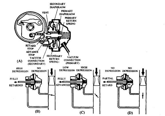
Fig. 16.16. Duel diaphragm vacuum control. A. The control system. B. Engine idling.
C. Part load. D. Full load.
Figure 16.16D shows the throttle in full open condition and a low depression acts in both chambers where both diaphragms are in the returned position. A strong secondary spring pushes the movable stop to the right. If this position is maintained the primary diaphragm advances the spark compared with the idling-timing. However, the centrifugal advance system provides the main control as the engine speed is high.
Rotor and Distributor Cap.
When the cylinder is set for firing, the spark plugs of a multi-cylinder engine are connected to the secondary winding of the coil. The distributor performs this job through a revolving rotor arm, which transmits the HT impulse to the appropriate fixed electrodes in the cap. Once the rotor arm tip is adjacent to the cap electrode, a spark jumps across the small air gap caused by the HT voltage. To convey the current to the spark plugs each electrode is connected to a highly-insulated cable.
A plan view of the distributor layout is shown in Fig. 16.17. The rotor arm is a press fit on a boss formed on the contact breaker cam. A positive drive is achieved at half crankshaft speed by engaging a projection of the rotor with a slot in the driving boss. A spring-loaded carbon brush or a strip spring fixed to the rotor arm makes the electrical contact between the centre king-lead terminal and the brass blade.
On some designs of rotor arms, the electrode end of the blade is projected towards the next electrode in the direction of rotation. This arrangement reduces the risk of the
engine running backwards. If the crankshaft starts to move backwards, the rotor provides the HT current to a plug of a cylinder whose piston is situated in the region of BDC instead of the firing position.
The distributor cap is made of a brittle, anti-tracking, phenolic material, moulded around the fixed electrodes and cable connections. The cap is normally secured with the help of quick-action spring clips with a provision to prevent entry of dust and water. Since the corrosive gases nitric oxide and ozone are produced during sparking, some form of ventilation or shielding is incorporated to prevent the damage to metal surfaces by the gases.
Ignition Distributor.
A distributor (Fig. 16.18A) houses the contact breaker, mechanical and vacuum advance mechanisms and the actual HT distributor. The shaft is supported in two sintered-iron bearings and the drive from the camshaft, at half crankshaft speed, is transmitted by a helical skew gear or by an offset male dog (Fig. 16.18B). The distributor is fixed to the engine by a plate and clamp, clamp bolt or body flange. The distributor has a provision to rotate its body partly for adjusting timing and the rotation against the direction of rotation advances the ignition.
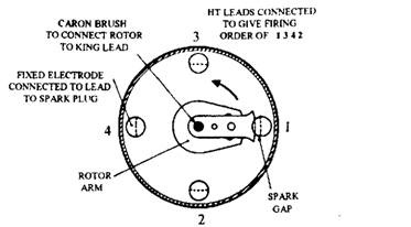
Fig. 16.17. Distributor in plan view.
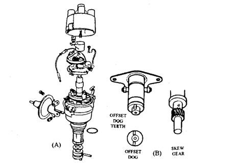
Fig. 16.18. Distributor and drives. A. Distributor. B. Drives.
High-tension Cable.
In the past, a rubber covered, multi-strand, copper lead was commonly used as HT cable. In recent time PVC is used in place of rubber, as this provides better protection from oil and water but is less effective than rubber for high temperatures operation. Whatever material is used, care is taken to prevent the shorting of HT current to earth.
Each lead should be kept clear of all low voltage cables and other HT leads to prevent problems due to mutual induction. Any leakage path reduces the voltage applied to the spark plug, which may produce cold-starting difficulties. Also moisture can create troubles if the leads are porous or when water comes into contact with the coil, distributor cap or spark plugs. In these cases an aerosol-applied silicon is sprayed for dispersing moisture as well as for sealing against moisture.
Radio-frequency energy, produced from a metallic HT cable of an ignition system, causes serious interferences to television and radio receivers even when they are placed at a considerable distance from the vehicle: Legislation limits this interference, and this is met by increasing the electrical resistance of the HT circuit at the cost of reduction of the capacity current that discharges each time a plug fires. This high resistance is obtained by using a special suppression cable for all HT leads. This special cable contains a core of graphite-impregnated, stranded and woven rayon or silk, which is insulated by a PVC, or Neoprene covering. Special connectors join the non-metallic cable core to the terminal of the component. The resistance of a typical cable is about 13000 – 26000 Q per metre. The cable resistance is maintained within the limits recommended to eliminate its effect on engine performance. Also by limiting the discharge current, the chance of burning of the distributor and spark plug electrode is reduced.
Ballast Resistor.
A ballast resistor fitted in the primary circuit improves cold starting and reduces the variation in coil output with respect to speed.
Cold-start Ballast Resistor.
The drop in a battery p.d., which occurs when an engine is cranked on a cold morning, lowers the coil voltage below that needed to produce a spark at the plug. A low voltage applied to a coil during operation of the starting motor is felt in a number of ways. In one case the engine does not start while the starting motor is operating, but it starts easily when it is bump started. Similarly, some engines do not start until the starter switch is released where the momentum of the crankshaft gives sufficient movement for the engine to fire. These situations however are not frequent nowadays. Beyond a period of about 5 seconds, the voltage output from many batteries falls considerably. On the other hand if the starter switch is released after a short time and is not re-applied for a few seconds, the battery then has a chance to recover.
Many cold starting problems have been overcome by using a ballast resistor, or a resistive cable between the battery and the ignition coil. In Fig. 16.19 a ballast resistor of 2 Q is connected in series with the ignition switch and a 7.5 V coil. With a 2.25 A current flow in the circuit the voltage drop across the resistor is 4.5 V. By designing a coil to suit the voltage of the ballast resistor used, the secondary output is kept within the limits required by the engine.
The cold starting of the engine is further improved by using an extra cable in parallel with the ballast resistor. The ends of this cable are connected to an additional terminal on the starter solenoid switch and the ignition coil. With the operation of the starter, solenoid coil receives the current, which by-passes the ballast resistor, so that full battery voltage, even though it may be only 10 V at this time, is applied to the coil.

Fig. 16.19. Cold start ballast resistor.
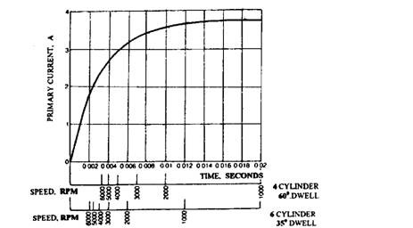
Fig. 16.20. Growth time for primary circuit.
Output Control Ballast Resistor.
Comparatively longer time is required for the primary current to build up to its maximum after the contact breaker has closed. Figure 16.20 presents the growth time for a typical ignition coil. A time of about 0.01 second is required, in this case, before the maximum primary current is attained.
When the contact breaker closes the current flow starts which continues to build up during the dwell period. Although the dwell angle is required to remain constant with speed, the dwell
time in seconds shortens. When the dwell time is less than about 0.01 second for this coil, the primary current is no longer capable of reaching its maximum; as a result the output from the coil gradually falls with increase in speed beyond this point.
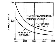
Figure 16.21 presents the variation in dwell time for 4-and 6-cylinder engines. Once the dwell time for a particular speed and engine is obtained from this graph, it is possible to determine the primary current at that speed using Fig. 16.20. These graphs indicate that with increase in speed, an engine with 6 or more cylinders suffers a gradual fall-off in coil output. An output control ballast resistor, if installed in series with the primary circuit, compensates for this variation in output.
Due to a high temperature coefficient of the iron-wire resistor, the hot resistance is about three times of the cold resistance. Since the temperature of the resistor depends on the current passing through it, the long dwell time causes the resistor to run hot when the engine is running at a low speed. As a result, the average current in the primary decreases so that the coil runs cooler and also the spark erosion due to high voltage is reduced. Also, the normal drop in primary current as the engine speed is increased permits the ballast resistor to run cooler. This causes reduction in its resistance value and as a result increases the primary current to offset the fall-off due to speed. This type ballast resistor has a cold value of about 0.25 Q.. The resistor can be installed either internally in the coil or externally in the circuit.
Low Inductance Ignition Coil.
The coil’s self-inductance limits the current growth in the primary winding of a coil. As the primary current gradually increases, self-inductance in the winding produces back emf which opposes any change in the current. This opposition to current growth also increases with the increase in the number of turns on the primary winding.
Engines with a large number of cylinders, especially 8-cylinder unit, need a coil capable of producing a quicker growth than conventional coil. Therefore, these engines use a high output coil, called a low inductance coil. As the primary winding of a low inductance coil has fewer turns, the wire is shorter in length due to which the current of about three times as great flows when the engine is stalled. Consequently the erosion wear, on a conventional contact breaker is high. As a result high current and hence the low inductance coil is often used in a transistorized breaker system.
Twin Contact Breaker.
Twin compact breakers are used to improve the short dwell time associated with high speed operation of 8-cylinder engines. This system reduces the breaking time of the primary circuit
ENGINE SPEED. RPM
Fig. 16.21. Variation in dwell time.
because it provides one set of contacts to make the circuit immediately after the spark has occurred.
Figure 16.22 illustrates a twin contact arrangement where the contact set A is connected in parallel with contact set B. Therefore, the circuit is interrupted only when both contacts are opened simultaneously. Once the contact set A opens to provide a spark at the plug, the other set closes to build up of the primary current. The twin contact arrangement has become obsolete due to the introduction of transistorized system.
16.2.3.
Magneto Ignition
A magneto is a self-contained unit capable of generating its own electricity and steps up the voltage to provide a spark at the plug at the correct time. It does not use a battery. The voltage output improves with the rise of the engine speed. These are two advantages of a magneto over a coil ignition system. The main disadvantage of this system is its low performance at cranking speed due to which the coil ignition system has become universal for cars. The magneto, however, is still in use with small engines such as motor cycles, mowers etc.
Rotating Magnet Magneto.
Small engines have incorporated this type of magneto due to the availability of permanent magnets with improved magnetic materials. A flywheel magneto uses the magnet, cast into a non-ferrous flywheel, and is classified as a rotating magnet type, the basic construction of which is shown in Fig. 16.23. In this design a laminated soft-iron armature contains the coil windings, and is stationary. A cam formed on the flywheel hub operates a contact breaker.
During the rotation of the magnet with the flywheel, an alternating magnetic flux passes through the armature. Since the primary coil is wound on this armature, a current is induced into the coil every time a change occurs in the magnetic flux. Movement of the magnet across the complete armature provides a full reversal of the flux, which gives rise to an alternating current that peaks every time the flux reversal occurs.
After the generation of its own primary current, the magneto transforms the low voltage to a voltage sufficient to produce a spark at the plug. For achieving this the circuit (Fig. 16.24) contains a contact breaker and two windings, a primary and a secondary, interconnected similar to that used in a coil ignition circuit but without battery. A capacitor in the circuit speeds up the collapse of the magnetic flux by reducing arcing at the contacts. The contact breaker is kept closed during the building up of the primary current to its maximum. The contact breaker is opened just before the primary starts to fall in order to build up in the other direction. This interruption mutually induces a high voltage into the secondary winding, which is connected to the spark plug.
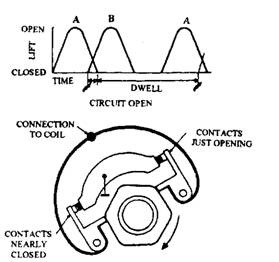
Fig. 16.22. Twin contact breakers.
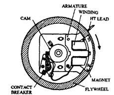
Fig. 16.23. Rotating magnet magneto.
Many magnetos incorporate a safety spark-gap to protect the insulation of the magneto coil when either a plug lead becomes disconnected or the HT is open-circuited.

Fig. 16.24. Circuit of magneto.
