25.6.
Constant-mesh Gear box
25.6.1. Four-speed and Reverse Single-stage
In this arrangement only a primary input shaft and a secondary output shaft are used, and hence all gear reduction takes place in a single stage, that means between only one pair of gear wheels (Fig. 25.12). The primary shaft carries a cluster of gears. The shaft and gears may be made as a single casting or forging, or the gear wheels may be splined or keyed on to the shaft. The output secondary shaft carries constant-mesh gearwheels, which revolve freely relative to it when not engaged.
First, Second, Third, and Fourth Gear Selection.
The power flow starts at the input primary shaft, which is then divided four ways to the output secondary shaft through first, second, third, and fourth output gears. These four output gearwheels in the neutral position are revolved by the meshing primary-shaft gear cluster about their own axes relative to the output secondary shaft. Each individual gear ratio is attained by sliding the appropriate outer dog-clutch hub towards and over the dog teeth of the particular gearwheel selected. Through this action the selected output gearwheel is engaged as well as locked to the output secondary shaft so that the power-flow path is completed.

Fig. 25.12. Four-speed-and-reverse single-stage constant-mesh gearbox.
Reverse-gear Selection.
In this layout, power flows from the input primary shaft to the reverse gearwheel. When the reverse sliding-mesh idler gear is slid into contact, power is transmitted from the primary reverse wheel to the reverse idler. The reverse-idler intern rotates the reverse output gear, which forms part of the first/second-gear dog-clutch outer hub. This produces a gear reduction, and a reverse gear drive is provided since the idler wheel changes the direction of rotation. It may be noted that in the forward gears, the output-gearwheel rotates in the opposite direction of the input shaft, but the reverse gear rotates in the same direction as the input gearwheel.
25.6.2.
Four-speed and Reverse Double-stage
The primary (input) shaft is splined at the flywheel end. It carries a first-stage constant-mesh helical gearwheel and a fourth-gear toothed dog clutch, formed on it at the gearbox end. At the flywheel end it is supported by a small bush or ball-bearing and at the gearbox end by a ball-bearing or taper-roller bearing (Fig. 25.13).
The lay-shaft holds cluster gears rigidly together. For small and medium sized gearboxes, the gears are normally cast or forged as a one-piece unit. For larger heavy-duty gearboxes, the gearwheels are separately machined and then held together on a splined lay-shaft. The lay-shaft is generally force fit at its ends in the gearbox housing and supports the one piece lay-cluster gears on needle-roller bearings recessed in the ends of the gear cluster. Thrust washers are installed between the gear cluster and the gearbox housing to absorb any side-thrust generated. In large heavy-duty gearboxes, the splined lay-shaft uses ball or taper bearings at its ends.
The main (output) shaft has sections with stepped diameter, some portions of which have smooth polished surface so that various gears can revolve relative to this shaft, while other portions are splined to cause power transmission from the drive path gears to the constant mesh sliding-dog clutch inner hubs. This shaft carries the first, second, third, and reverse final output reduction gearwheels, which are free to revolve relative to this shaft and are in constant mesh with the laycluster gearwheels. Additionally, this shaft supports the first/second, and third/fourth-gear sliding-dog-clutch inner hubs, fixed to the shaft by spines. To facilitate the assembly of main shaft, output gears, and hub, one end of the shaft has a reduced-diameter-spigot plain bearing surface. This end carries a needle-roller bearing, which fits into a recess in the primary-shaft gear end. The other (output) end of the shaft is supported by either ball or taper bearings located in the gearbox housing.
The sliding dog clutch is a positive locking device, whose purpose is to allow the power flow from the primary-shaft to the output shaft when the friction clutch has disengaged the gearbox from the engine. The dog clutch has an inner and outer hub. The inner hub contains both internal and external splines and is fixed to the output main shaft through internal spines. The outer hub carries a single groove formed round the outside to position a selector fork and is internally splined to mesh with the exterior spines of the inner hub.
When a gear is selected, the speeds of both the input and the output shafts are initially equalized either by allowing the engine speed to drop when changing up to a upper gear or by revolving the engine slightly when changing into a lower gear. The outer hub is then slid over the dog teeth of the particular gear chosen. This action provides a positive means of transmitting power through the compound gear train. (An alternative type sliding dog clutch is shown in Figs. 25.28 and 25.29).

Fig. 25.13. Four-speed-and-reverse double-stage constant-mesh gearbox.
First, Second, and Third Gear Selection.
The power flow takes place from the input shaft to the lay-cluster gear through the first stage constant-mesh gear. The power path then follows three routes to the main shaft, through first, second, and third output gearwheels. In the neutral position meshing lay-cluster gear drives these three output gearwheels, but main shaft itself does not revolve. To select individual gear ratio the outer dog-clutch hub is slid towards and over the dog teeth forming part of the required gearwheel. This engages and locks the selected output gearwheel to the output main shaft, thereby completing the power-flow path.
Top-gear Selection.
In top or fourth gear, there is no gear reduction; instead a direct power-flow path is established from the input to the output shaft. On the engagement of top gear, the third/fourth-gear dog-clutch hub is slid over the dog teeth cut on the input shaft, thus allowing direct power transmission from the input primary shaft to the output main shaft. All the other constant-mesh gearwheels supported on the main shaft revolve about their axis at their own speeds relative to the main shaft, when they are engaged.
Reverse-gear Selection.
When the reverse sliding-mesh idler gear is slid into mesh, it transmits motion from the lay-cluster reverse gearwheel to the reverse idler and then to the reverse output gear, which forms part of the first/second-gear dog-clutch outer hub. This provides a second stage gear reduction. The idler wheel changes the direction of rotation and so provides a reverse gear train.
Referring Fig. 25.13 with Fig. 25.11 it can be concluded that expression for all forward gears remains same for both sliding and constant mesh gears. In case of reverse gear, the power flow taken from A to B and then from I to J through the idler gear. The idler changes the direction of rotation of main shaft without affecting the gear ratio.
![]()
The essential difference between sliding-mesh and constant-mesh gear box is that in a sliding-mesh gear box the gears are actually slide along the main shaft to engage or disengage their respective mating gears on the lay-shaft. Whereas in the constant-mesh gear box the lay-shaft and main shaft gears are in constant-mesh. The main-shaft gears are designed to revolve freely and are engaged by sliding dog clutches splined to the main shaft, so that the particular gear is locked to transmit power.
The problem of side thrust on helical gears experienced with sliding-mesh gear transmission is eliminated in constant-mesh gear transmission, as the gears do not slide. The difficulty in the constant-mesh gearbox of bringing the in put and output shafts to the same speed when changing gear has been overcome by the development of the synchromesh gearbox.
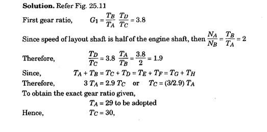
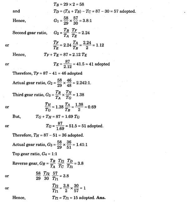
Example 25.1. Sketch a section through a sliding type gear box with four forward and one reverse speeds and explain clearly how the different speed ratios will be obtained in the following cases :
Gear ratio on top gear = 1:1 Gear ratio on third gear = 1.38:1 Gear ratio on second gear = 2.24 :1 Gear ratio on first gear = 3.8:1 Gear ratio on reverse gear = 3.8:1
Assumed counter shaft or layout shaft speed is half that of the engine speed and the smallest gear is not to have less than 15 teeth.
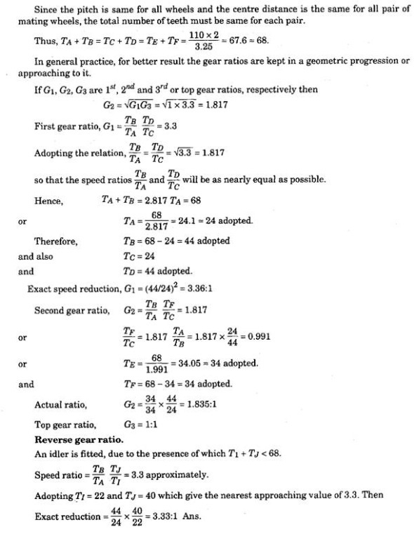
Example 25.2. An automotive gear box gives three forward speeds and one reverse with a top gear of unity and bottom and reverse gear ratio of approximately 3.3:1. The centre distance between the shafts is to be 110 mm approximately. Gear teeth of module 3.25 mm are to be employed.
Sketch the layout of a typical constant mesh gear box for these conditions giving the number of teeth for the various gear wheels and showing closely how the different ratios are obtained.
Solution. Refer Fig. 25.13.
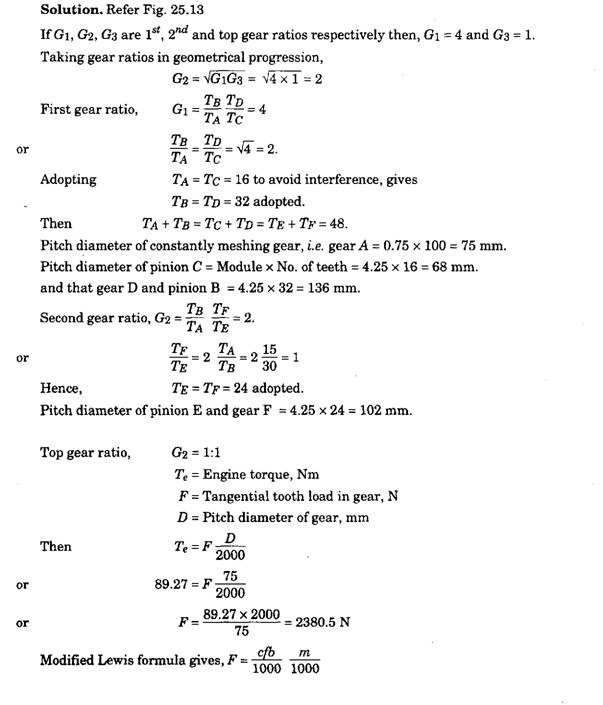
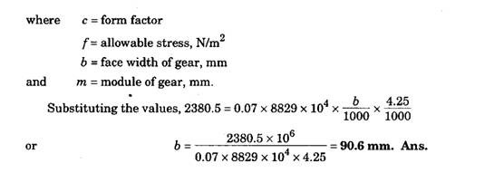
Example 25.3. The maximum gear box ratio of an engine 75 mm bore by 100 mm stroke is 4. The pitch diameter of the constantly meshing gear is 75% of the piston stoke. Taking the module as 4.25 mm calculate the size and number of teeth of gears for a three speed gear box. Calculate the face width of the constantly meshing gear using the modified Lewis formula. The engine torque is 910 kgf-cm, value of constant in the Lewis formula is 0.07 and the allowable stress is 900 kgfl cm . Draw the neat sketch of the three speed gear layout.
