27.3.
Condition for True Rolling
True rolling occurs only when<the direction of motion of the vehicle is perpendicular to the wheel axis (Fig. 27.22A), i.e. the wheel is subjected to forward force. When wheel is subjected to side force that acts parallel to the wheel axis, a true scrub action is produced (Fig. 27.24B). When the wheel is subjected to both forward and side forces, the movement is compounded of true rolling and lateral distortion (Fig. 27.22C). This condition occurs when the wheels are being steered, i.e. the direction of motion is neither parallel nor perpendicular to the axis of rotation.
On a circular path, true rolling condition occurs when the projected axes of several wheels all moving in different curved paths intersect at a single point called the instantaneous centre
(Fig. 27.22D). When these projected axes do not intersect at a single point, a degree of tyre scrub results (Fig. 27.22E).

Fig. 27.22. Road-wheel and tyre rolling conditions. A. True-rolling. B. True scrub. C. Tyre steer.
D. Condition for true rolling. E. Condition for tyre scrub.
Whenever a vehicle takes a turn, the front wheels must turn in a definite manner both in relation to each other and to the axis of the rear wheels so that the lateral slip may be avoided

Fig. 27.23. Condition for true rolling of a vehicle.
and true rolling for all the wheels is obtained. For this, as explained above, all the wheels must always rotate about the instantaneous centre. Since the rear wheels have a common and fixed axis, it is quite obvious that this common centre, 0, would lie somewhere on its extension (Fig. 27.23).

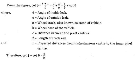
This equation gives the fundamental condition to be satisfied by all types of steering mechanism if true rolling for all the wheels is to be obtained avoiding any lateral slip. The steering linkage used in the vehicles must maintain the proper angles with the wheels when taking a turn. But practically it is not possible to maintain absolutely correct angles for the wheels for all turning angles.
Turning Circle Radius.
When a vehicle takes a turn without experiencing any lateral slip, all the wheels rotate about a common centre along different turning circles (Refer Fig. 27.23).

Thus the turning circle radius can be defined in different ways. In order to avoid confusion, the Society of Automotive Engineers (SAE) adopted the following definition. “The turning radius of an automotive vehicle is the radius of the arc described by the centre of the track made by the outside front wheel of the vehicle when making its shortest turn”. The turning radius depends upon a, b, c and the maximum angle 0 through which the inside front wheel can be deflected from the straight-ahead position. Thus R0f when expressed in these parameters becomes,

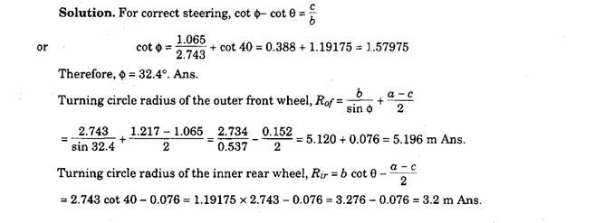
Example 27.1. A motor car has a wheel-base of2.743 m and pivot centre of 1.065 m. The front and rear wheel track is 1.217 m. Calculate the correct angle of outside lock and turning circle radius of the outer front and inner rear wheels when the angle of inside lock is 40°.

