33.6.
Components of Refrigeration System
The components of the refrigeration system working in a vapour Compression cycle are shown in Fig. 33.5. The major components are compressor, condenser, receiver-drier, expansion valve, and evaporator. The compressor pumps heat-laden refrigerant vapour from the evaporator. The refrigerant is compressed in the compressor and then is sent, under high pressure to the condenser as a superheated vapour, which gives up its heat to the ambient while flowing through the condenser fins and thereby changes to a liquid. The condensed liquid refrigerant is filtered, dried, and temporarily stored, under pressure, in the receiver-drier. Liquid refrigerant is metered from the receiver-drier into the evaporator by the thermostatic expansion valve, which controls the flow of refrigerant in this part of the system. The refrigerant pressure is lowered by the expansion valve, due to which the refrigerant begins to boil and change to a vapour. During this process the refrigerant picks up heat from the warm air passing through the fins of the evaporator. This heat is transmitted first to the compressor, and then to the condenser for dissipation. Thus the process repeats.

Fig. 33.5. Components of a typical refrigeration system.
33.6.1.
Receiver-drier (Dehydrator)
The load on the evaporator varies due to increase in temperature, increase in humidity, or loss of refrigerant. The receiver-drier shown in Fig. 33.6 holds extra refrigerant to meet the load fluctuations in the evaporator. It is a cylindrical metal can with two fittings and in most cases, has a sight glass. It is located in the high pressure side of the air conditioning system. The construction of the receiver-drier is such that it separates refrigerant vapour and moisture, and ensures steady flow of 100% moisture free liquid to the thermostatic expansion valve. The assembly can be divided into two parts; the receiver and the drier. The receiver section stores proper quantity of refrigerant in order to maintain steady flow. And the drier section of the tank is usually an inline type and contains a filter and a desiccant or drying material. A sight glass, installed at the outlet of the drier, allows the service technician to observe the refrigerant flow in the system. The sectional view of the receiver-drier in Fig. 33.7 shows its different components.
The functions of receiver-drier in brief are (i) to receive and store liquid refrigerant for the evaporator,
(ii) to filter out any dirt from the refrigerant, (Hi) to absorb mdisture if present in the refrigerant, and (iv) to trap any refrigerant vapour that did not condense in the condenser.

Fig. 33.6. Receiver-drier assembly (three types).
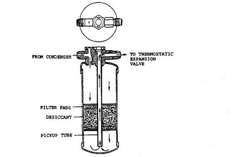
Fig. 33.7. Sectional view of receiver-drier.
Desiccant.
The desiccant used commonly in the drier is silica gel or molecular sieve, which is placed between two screens as shown in Fig. 33.7. The capacity of the desiccant for absorbing
moisture depends upon the volume and type of desiccant used. Silica gel of 82 cm can absorb and hold about 100 drops of water at 340 K. As temperature increases, the ability of the desiccant to hold moisture decreases. Therefore location of the receiver-drier has a direct affect on its ability to absorb and hold moisture. When the desiccant reaches its saturation point, some of its moisture is released into the system. As little as one droplet of moisture, if collected inside the thermostatic expansion valve and changed to ice in the valve orifice, can block the flow of refrigerant and consequently stops the cooling action.
Filter.
In most cases the filters are installed in driers (Fig. 33.7) on both sides of the desiccant through which the refrigerant passes before leaving the tank. The filters arrest dust and other solid materials, which otherwise could have carried into the system. In the absence of the filter, driers depend on the strainer for the removal of all foreign particles.
Pickup Tube.
The liquid refrigerant is collected at the bottom of the tank and the gaseous part of the refrigerant remains at the top. The pickup tube, which extends to the bottom of the tank, permits only liquid refrigerant to be fed to the thermostatic expansion valve.
Strainer.
Irrespective of filters, the receiver-drier always has one or two strainers on either side of desiccant to arrest foreign particles in the refrigerant besides holding the desiccant in place. The strainer is made of fine wire mesh.
Sight Glass.
The sight glass is used to observe the flow of refrigerant in the system. It can be located at any point in the liquid line. When the system is operating properly, a steady stream of liquid free of bubbles can be seen in the glass. Presence of bubbles or foam often indicates a system malfunction or a shortage of refrigerant. However in a cool day when ambient temperature is below 295 K, the continuous formation of bubbles is quite normal.
Accumulator.
Some air conditioners use an accumulator (Fig. 33.8) to prevent liquid refrigerant from entering the compressor. The accumulator also serves as a tank to store excess liquid refrigerant and contains a desiccant. The desiccant in the accumulators serves the same function as in receives-drier. Liquid refrigerant is collected at the bottom of the tank. Refrigerant vapour remains at the top of the tank, and is passed to the compressor through the pickup tube. At the bottom of the tank, the pickup tube contains a small hole or orifice, which allows a very small amount of trapped oil or liquid refrigerant to return to the compressor, without damaging the compressor. The accumulator cannot be serviced unlike the receiver-drier, and hence if found defective, has to be replaced.

Fig. 33.8. Cutaway view of the accumulator.
33.6.2.
Thermostatic Expansion Valve (TXV or TEV)
The thermostatic expansion valve controls the amount of refrigerant entering the evaporator to match the varying heat load conditions and is located at the inlet side of the evaporator. In addition, it separates the high pressure side of the system from the low pressure side. The expansion valve changes the medium temperature, high pressure liquid refrigerant coming from the condenser to the low temperature, low pressure liquid entering the evaporator.
The quantity of refrigerant passing through the valve is controlled by the temperature and pressure at the evaporator outlet. At idle conditions, the temperature is about 286 K while at a higher speed, the temperature goes down to about 275 K and sometimes slightly lower. The expansion valve opens when the evaporator outlet temperature rises 5.5 to 8.3 degrees above the refrigerant boiling point and closes when the temperature falls 5.5 to 8.3 degrees below the refrigerant boiling point. The expansion valve controls the refrigerant flow maintaining the evaporator outlet temperature nearly constant. The amount of heat transferred to the evaporator controls the evaporator temperature and during this process the refrigerant liquid is converted into vapour in the evaporator. The quantity of refrigerant converted into vapour increases with the increase of the evaporator heat load.
The expansion valve does not satisfactorily control minimum temperature throughout the wide range of engine driven compressor speeds found in automobiles. If the evaporator temperature falls below the freezing point of water, the condensed moisture freezes thereby plugging the air flow passage which prevents air cooling. To overcome this problem, a thermostatic switch is installed, which senses the evaporator temperature. If the temperature approaches freezing point, the thermostatic switch disengages the compressor clutch to stop the refrigerant cycle and subsequently when the evaporator temperature goes up the compressor is again engaged to start the cycle.
The refrigerant R-12 has a boiling point of 243.27 K ( – 29.9°C). The liquid refrigerant delivered to the evaporator completely evaporates due to absorption of heat in the evaporator and becomes superheated at the coil outlet or tailpipe. All expansion valves are adjusted to attain superheated condition.
The remote bulb is the sensing element of the expansion valve, which is attached to the evaporator tailpipe to sense outlet temperature. Due to superheat, the evaporator outlet temperature becomes some what higher than the temperature at which evaporation takes place. This causes to increase the temperature of the inert fluid within the remote bulb, so that corresponding higher pressure is exerted on the top of the diaphragm. This pressure is greater than the combination of both the evaporator pressure and the superheat spring pressure. As a result the needle valve opens until the pressure on both sides of the diaphragm is equal.
The construction of a thermostatic expansion valve is illustrated in Fig. 33.9. The valve has an orifice of about 0.2 mm diameter with a needle type valve and seat to provide variable
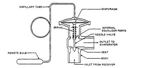
Fig. 33.9. Thermostatic expansion valve.
metering. The needle is actuated by a diaphragm, which is controlled by three forces as follows :
(t) The pressure of the inert fluid in the remote bulb or capillary tube against the top of
the diaphragm which tends to keep the valve open. (ii) The evaporator pressure exerted on the bottom of the diaphragm, which tends to keep
the valve closed.
(Hi) The superheat spring pressure exerted on the bottom of the needle valve, which tends to keep the valve closed.
The thermostatic expansion valve performs three main functions; throttling, modulation, and control.
Throttling Action.
A drop in refrigerant pressure in the expansion valve is accomplished without changing the state of the refrigerant. Hence high pressure liquid becomes low pressure liquid.
Modulating Action.
The thermostatic expansion valve meters the required amount of liquid refrigerant into the evaporator for proper cooling action, which varies with the evaporator heat loads.
Controlling Action.
The expansion valve is designed to change the amount of liquid refrigerant metered into the evaporator in response to load or temperature changes. The flow of refrigerant to the evaporator is directly proportional to the heat load.
A typical thermostatic expansion valve is shown in Fig. 33.10. The valve is consisted of seven major parts :
(a) Body (b) Valve seat (c) Diaphragm
(d) Push rods (e) Valve steam or needle (/) Superheated spring with adjuster (g) Capillary tube with remote bulb.
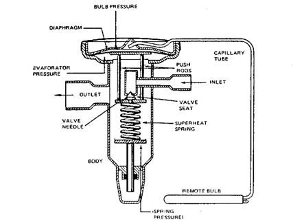
Fig. 33.10. Typical thermostatic expansion valve.
Two types of thermostatic expansion valves in common use are the internally equalized valve and the externally equalized valve. In an internally equalized valve there is a drilled passage from the evaporator side of the needle valve to the underside of the diaphragm. An externally equalized valve picks up the evaporator pressure at the outlet of the evaporator. The external equalizer tube is connected to the tailpipe of the evaporator and runs to the underside of the diaphragm. In both the cases, the effect of the pressure drop across the evaporator coil is eliminated. As a result, the superheat setting depends only on the adjustment of the spring tension.
33.6.3.
Evaporator
The evaporator, shown schematically in Fig. 33.11, is a heat exchanger where the refrigerant picks up heat from the air and vaporises. The factors considered in the design of the evaporator are size and length of the tubing, the number of fins, and the amount of air passing through and past fins, beside heat load, which is the amount of heat to be removed.
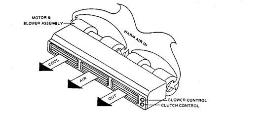
Fig. 33.11. Evaporator.
The refrigerant that leaves the evaporator on its way to the compressor is a low pressure gas. If excess refrigerant is metered into the evaporator it floods. As a result proper cooling effect is not produced because refrigerant does not vaporize properly. Also there is possibility of liquid refrigerant leaving the evaporator, so that the compressor may be damaged. If less refrigerant is metered into the evaporator, the unit once again does not produce adequate cooling as refrigerant vaporizes too rapidly before it passes through the evaporator coil. The evaporator in this condition is said to be starved.
33.6.4.
Compressor
The compressor is a specially designed pump for use in the refrigeration system and performs two important functions at the same time.
(a) It creates a low pressure condition at the compressor inlet to remove heat-laden refrigerant vapour from the evaporator due to which proper amount of liquid refrigerant is admitted into the evaporator.
(b) It compresses the low pressure refrigerant vapour to a high pressure vapour, thereby increasing both pressure and temperature of refrigerant.
Therefore failure in any of the functions of compressor causes reduction in circulation of the refrigerant, consequently air conditioning system does not function properly or at all.
Types.
The compressor may be of reciprocating (piston type) as shown in Fig. 32.12A, B and C, or vane rotary type shown in Fig. 33.12D. In reciprocating compressors, pistons move up and down, to and fro, or back and forth in cylinders. The compressor have various configuration. Rotary compressors are of van rotary type.
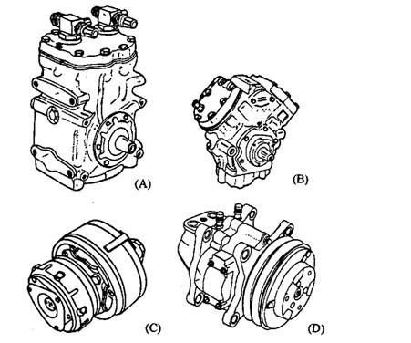
Fig. 33.12. Refrigerant compressor. A. Two cylinder square type. B. Two cylinder V-type.
C. Four cylinder round compressor. D. Van rotary compressor.
Many different models of compressors are found on today’s cars. Depending upon the design, the compressors have one, two, four, six or ten cylinders. All the models are generally of the reciprocating type except York’s Vane Rotary compressor which was introduced in the early 80′s. The prime consideration and need for new compressor design is reduction of weight.
Driving System.
The basic methods of driving the pistons of the compressor are crankshafts and axial plates. Driving the piston by a crankshaft is similar to as in an automobile engine, the difference being that in the compressor a crankshaft drives the piston, where as in the engine the piston drives the crankshaft. In axial plate drives, the plate is pressed on the main shaft and gives a reciprocating motion to the piston. During one complete revolution of the crankshaft, the piston is driven from one end of its travel to the other by action of the axial plate, which rotates with the crankshaft. Both crankshaft and axial plate of the compressor are driven by the engine crankshaft, directly or indirectly, by means of pulleys and belts.
All automotive air-conditioning compressors have an electromagnetic clutch, attached to their crankshaft or main shaft in order to start or stop the compressor (Fig. 33.13). The clutch includes a coil, which is attached to the compressor housing. The compressor pulley is mounted on ball bearing so that it can run freely when the clutch is disengaged. The coil is connected to the battery by the cycling switch. The flow of current in the coil produces a magnetic field, which magnetically locks the pulley to the clutch-plate and hub assembly.
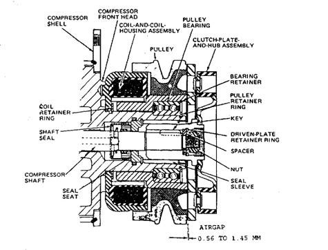
Fig. 33.13. Magnetic clutch (sectional view).
Some compressors are driven by the engine crankshaft via one or two belts and have an idler pulley (Fig. 33.14A), which is used to adjust the belt tension. Some use an accessory device, such as an alternator or power-steering pump pulley (Fig. 33.14B) as the provision for belt adjustment. Other compressors are driven off the water-pump pulley, which in turn is driven by the engine crankshaft pulley (Fig. 33.14C) and the belt in this case is tensioned by adjusting the compressor. Compressors are also driven off the crankshaft by a single-belt drive (Fig. 33.14D) along with another accessory called a serpentine drive. This arrangement is tensioned by a spring-loaded idler pulley.
Operations.
Reciprocating Type.
Each piston of the compressor is equipped with a set of suction and discharge valves and valve plates. The piston draws in refrigerant vapour through the suction valve and forces it out through the discharge valve. While one piston is on the intake or suction stroke, the other is on the compression or discharge stroke. The piston is fitted with a piston ring to provide a seal between the piston and cylinder wall, which helps to produce a negative (low) pressure during the intake stroke, and a positive (high) pressure during the exhaust stroke.
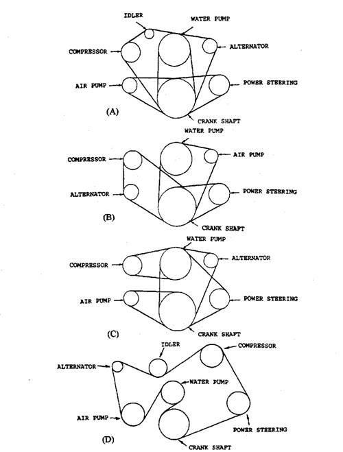
Fig. 33.14. Belt driving system for the compressor.
During the intake stroke (Fig. 33.15A) low pressure is created at the top of the piston and below the intake and discharge valves. The higher pressure in the evaporator line opens the intake valve to admit refrigerant vapour into the cylinder chamber. A much higher pressure at the top of discharge valve prevents it from opening during intake stroke. During compression stroke (Fig. 33.15B), due to high pressure above the piston the intake valve is closed and the
discharge valve is opened. This allows the compressed refrigerant vapour to be discharged from the compressor. The suction stroke or compression stroke takes place at half of the crankshaft revolution.
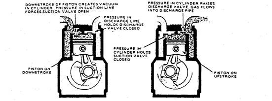
Fig. 33.15. Operating cycle of the reciprocating compressor.
The compressor is equipped with service valves, which are used to service the air-conditioning system. The manifold and gauge set are connected into the system at the service valves. Evacuation and charging the system are carried out through the manifold and gauge set. Refrigerant oil is stored in the compressor sump to keep the crankshaft, connecting rods and other internal parts lubricated. The hose at the compressor outlet contains high pressure refrigerant vapour and hence is made of synthetic rubber with extended preformed metal (steel or aluminium) ends and fittings.
Rotary Compressor.
York’s van rotary compressor (Fig. 33.12D) provides the greatest cooling capacity per kg of compressor weight. It has a van and a discharge valve. The discharge valve also serves as a check valve to prevent the entering of high pressure refrigerant vapour into the compressor during off-cycle or non-operation of the compressor. The vans rotate with the shaft in this model.
Variable Displacement Compressor.
In 1985, Delco Air introduced a variable displacement compressor, which can match any automotive air-conditioning load demand under all operating conditions. This is accomplished by varying the displacement of the compressor by changing the stroke of the pistons. The five axially oriented pistons are driven by a variable-angle wobble plate. The angle of the wobble plate is changed by a bellows-activated control valve located in the rear head of the compressor. The control valve senses suction pressure, and controls the wobble plate angle based on crankcase-suction pressure differential. The angle of the wobble plate is actually changed by a force balance on the five pistons. Only a slight change in the crankcase suction pressure differential is sufficient to create a force on the pistons resulting in a movement of the wobble plate. Temperature, then, is maintained by varying the capacity of the compressor and not by cycling the clutch ON and OFF. This is a more uniform method of temperature control eliminating some of the noise problems associated with a cycling clutch system.
When the air-conditioning load is low and the suction pressure reaches the control point, the control valve bleeds discharge gas into the crankcase, and, in-turn closes a passage from the crankcase to the suction plenum. On the other-hand, when the load is high, suction pressure reaches above the control point, and the control valve maintains a bleed from the compressor crankcase to the suction side. Hence there is no crankcase pressure differential so that the compressor reaches the maximum displacement causing the wobble plate to attain the maximum angle, and providing the largest stroke.
33.6.5.
Condenser
The condenser (Fig. 33.16) is a heat exchanger, and its function is just the opposite of the evaporator. The heat is removed from the refrigerant vapour in the condenser so that it can be converted to liquid. Practically, 100% conversion to liquid does not take place, and the small percentage of the gaseous refrigerant leaving the condenser does not affect the operation of the system as it is entrapped in the receiver-drier.
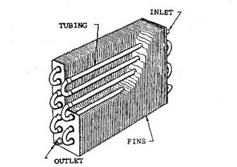
Fig. 33.16. Condenser.
The inlet to the condenser is at the top of the unit so that the condensing refrigerant can flow to the bottom of the condenser where it is forced, under pressure, to the receiver-drier through the liquid line. The liquid line from the condenser can be either a rubber or a metal line in a variety of sizes. The factors, which are involved in the design of condenser, are size and length of tubing, the number of fins, amount of air passing through and past fins, and the heat load.
33.6.6.
Hoses and Fittings
Refrigerant liquid and vapour hoses may be of copper, steel, or aluminium. They are usually made of a synthetic rubber strengthened by nylon braids. The inner core is usually of Buna ‘N’, a synthetic rubber, which is not affected by R-12. Normally, hoses of 8 mm ID are used for liquid line, 10 mm or 12 mm ID for vapour line, and 12 mm or 16 mm ID for suction line. Two types of fittings used in the air-conditioning system are flare fittings and O-ring fittings.
33.6.7.
Service Valves
The service valve provides a means to connect the manifold and gauge set into the system in order to perform diagnostic, testing and service procedures. Most of the air-conditioning systems have two service valves, one on the low pressure side (evaporator outlet) and one on the high pressure side (condenser inlet/compressor outlet) of the system. Some models also incorporate a third valve on the low pressure side of the system. Figure 33.17 shows the position of these valve. Two types of service valves are in use; the Schrader (automatic) valve and the hand shutoff (manual) valve.
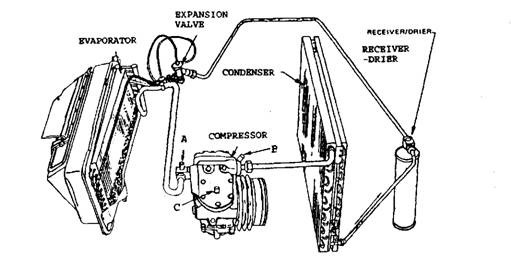
Fig. 33.17. Location of service valves in the system. A. Evaporator outlet (low pressure side). B. Compressor outlet (high pressure side). C. Compressor inlet (low pressure side).
Schrader Valve.
This valve is very similar to a tyre valve and is the most popular service valve today. The valve, shown in Fig. 33.18, has only two positions; cracked (open) and back seated (closed). The valve is opened or closed by a pin or bar at the end of the manifold hose or in a special hose adapter. Whenever the hose or adapter is screwed onto the Schrader valve, the system pressure is impressed on the corresponding gauges.

Fig. 33.18. Schrader valve and fitting for the hose.
If the hoses and/or adapters are connected or disconnected from a Schrader fitting without connecting the valve to the gauge manifold, there is a loss of refrigerant and likelihood of personal injury, and hence such a situation is to be avoided.
Hand Shutoff Valve.
The hand shutoff valve, also called as a manual valve, is still found on some systems. The hand shutoff valve has a 6 mm square end stem, used for opening and closing with the help of a wrench. The service valve is front seated when the stem is turned fully clockwise (Fig. 33.19A). In this position the refrigerant flow is shut-off and is trapped in the hose side of the service valve. And the gauge port is not a part of the system rather it connects to the compressor only. Operation of the compressor in this position may damage it as there is no outlet for the flow of the compressed refrigerant.
The service valve is back seated when the stem is turned fully counter clockwise (Fig. 33.19B). In this position the compressor is connected to hose outlet so that refrigerant is free to flow. However, the gauge port is closed, so pressure readings cannot be taken. Service valve should be in this position when the system is operating normally. When service valve is mid-positioned (Fig. 33.19C), it is in the cracked position. In this case the system can be operated while pressures are recorded through the gauge port openings.
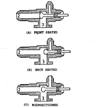
Fig. 33.19. Hand shutoff service valve. A. For connection of gauge. B. For connection of hose.
C. For connection with the compressor.
