24.7.
Clutch Operating Linkage
The clutch unit is a rigid part of the flywheel and hence the crankshaft assembly. It is therefore subjected to the engine and transmission vibrations such as rocking, shaking and pitching. The clutch foot-pedal assembly, on the other hand, is attached to the body structure. As a result, this may be subjected to slight bump and rebound movements of the body. For smooth operation of the clutch without any jerks, some sort of flexible linkage system must be incorporated, which does not interfere with the clutch adjustment, is compact, needs very little maintenance, has a long working life, is simple, and is reasonably cheap. The three basic methods of transmitting movement and force to the clutch from the foot pedal are
(i) rod linkage,
(ii) cable linkage, and (Hi) hydraulic system.
The early vehicles mostly used rod linkage system to actuate the clutch, but presently cable and hydraulically operated systems are being used. Only a few commercial vehicles still have the rod linkage.
24.7.1.
Rod-operated Linkage
Figure 24.12 illustrates two foot-pedal arrangements such as a chassis-mounted pedal and a bulkhead positioned pedal lever, the later finds more use in tilt-cab. The clutch operating mechanism connecting to the engine is enclosed in the clutch bell-housing and uses a cross-shaft. A fork-arm, which supports a thrust bearing and saddle, is clamped to the cross-shaft. One end of the cross-shaft extends outside the bell-housing and a withdrawal lever is attached to it. This lever is connected to the foot-pedal either directly by means of the withdrawal rod for the chassis-mounted foot-pedal or by a relay lever to transfer the horizontal withdrawal movement into a vertical one for the bulkhead pedal layout. As the clutch driven-plate wears the adjustment in both the layouts is carried out either by a screw-nut or by a turnbuckle. A pedal adjustment stop is provided with both linkages, for positioning the pedal suiting to the driver’s foot and, in the case of the chassis-mounted pedal, clears the floorboards.
As the clutch pedal is pressed, it pivots about the mounting bracket and the withdrawal rod pulls back or forwards according to the arrangement. Consequently the withdrawal lever rotates the fork-arm about the cross-shaft and pushes the thrust-bearing saddle against the clutch release-plate. This causes the movement of the release levers towards the flywheel, so that they pivot about the eyebolt pins, withdrawing the pressure-plate from the driven-plate thereby interrupting the drive.

Fig. 24.12. Rod-operated clutch arrangement.
24.7.2.
Cable-operated Linkage
Cable linkage is a popular and effective method of transferring movement from the pedal to. the clutch. The cable assembly uses an inner multi-strand steel-wire core and an outer cable sheath of a spiral wound flexible sleeve normally with nylon end-pieces. This plastic sleeve provides very good rubbing wear properties without requiring in general any lubrication. Also the inside of the sleeve may be lined with anti-friction material such as polytetra fluorethylene (PTFE) plastic to minimise any slip-stick friction.
The cable is run between the clutch bell-housing and the car bulkhead, where the pedal is normally located. A screw adjustment is incorporated at either the pedal or the bell-housing end to alter the length of the outer cable sleeve, for increasing or decreasing the free-play of the inner cable.
Mostly nowadays the thrust bearing is supported on an extended tube mounted over the gearbox primary input shaft for free sliding in the perpendicular direction of the bearing against the clutch release fingers. This causes application of equal pressure to all the release-fingers and ensures even loading of the diaphragm spring and pressure plate.
From the cable the leverage is relayed through a pressed steel release-fork lever to the thrust bearing. A spherical headed bolt pivots the lever end. The thrust bearings are mounted at about one third the length of the lever from the pivot. The outer end of the lever extends outside the bell-housing and is connected to the inner cable. When the clutch is disengaged, the inner cable is subjected to tension and the outer sleeve into compression. The fork-lever then tilts about its pivot forcing the release bearing against the release-fingers to disengage the drive.

Fig. 24.13. Cable-operated clutch arrangement.
24.7.3.
Hydraulically-operated Linkage
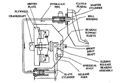
A more convenient way to transmit force and movement is by hydraulic linkage in which the fluid is forced through a flexible plastic pipeline, spun between the foot-pedal and the clutch bell-housing. A master-cylinder, mounted on the bulkhead and a push-rod joining the clutch-pedal to the sliding piston, provides the control of the clutch action. A slave cylinder unit containing the piston, is installed on an extension formed on the bell-housing flange. The slave piston relays the slightest movement to the fork-lever through the slave pushrod. The thrust bearing assembly is fixed to one end of the fork lever, and a spherical pivot is installed slightly in from this end.

Fig. 24.14. Hydraulically-operated clutch arrangement.
The master-cylinder piston pushes a continuous column of fluid through the pipeline when the clutch pedal is pressed down. This causes the displacement of an equal volume of fluid into the slave-cylinder due to which the piston moves out and tilts the fork lever. This causes the thrust bearing to defect the release-fingers so that the driven-plate is slipped.
When the pedal is released, engagement of the clutch occurs due to which the fluid returns to the master-cylinder and its reservoir. The return-spring in the slave-cylinder then maintains a slight pressure on the fork-lever for a continuous contact of the thrust bearing with the release-fingers.
Driven-plate wear, in this system, is compensated by the slave return-spring and piston automatically moves to take up the increased fork-lever tilt. The hydraulic actuating mechanisms are independent of frictional wear unlike cables due to application of large leverage. This system is particularly suitable for heavy-duty vehicles such as on large trucks.
24.7.4.
Vacuum-operated Clutch
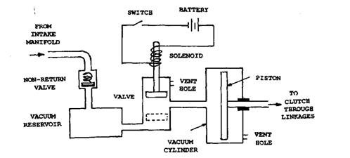
In this type of clutch, engine intake manifold vacuum is used for disengaging the clutch (Fig. 24.15). It uses a vacuum reservoir connected to the intake manifold through a non-return valve. It has a vacuum cylinder and piston, the rod side of the piston is opened to the atmosphere. The solenoid valve is operated when the switch is closed so that the circuit is complete. The switch is mounted on the gear lever so that when the gear lever is operated to change the gear, the switch is also closed.

Fig. 24.15. A typical layout of the vacuum operated clutch arrangement.
In the normal position the valve rod is in the bottom position of the valve (shown dotted in Fig. 24.15) and the switch is open. At this stage, the pressure on both sides of the piston in the vacuum cylinder is atmospheric. When the switch is closed due to the operation of gear change lever, the solenoid coil is energized and the valve rod is pulled up. This action opens the passage between the reservoir and the vacuum cylinder, so that a pressure differential acts on the piston of the vacuum cylinder. As a consequence the piston moves in the forward direction, causing the operation of linkage to disengage the clutch.
