14.5.
Charging System Limitations and Solutions
The charging system of a vehicle has to perform under varied conditions. Some indication of the power output has been given in the last section. If two of the operating conditions that may be encountered are considered, the complicacy of the task of producing the required output can be well understood.
Consider first the scenario of a traffic jam on a cold night in the rain involving long periods of engine idling, while near all electrical devices are in use. In the second scenairo, the car has been parked in the open on a frosty night. The engine is started, and seat heaters, heated rear window and blower fan are switched on while the screen and v/indows are scrapped for a few minutes. All the lights and wipers are now switched on to follow a journey of half an hour through busy traffic. It is considered that the seat heaters and heated rear are switched off automically after aboutl5 minutes.
Tests and simulations on the above examples as well as many others indicate that at the end of the first scenario the battery’s state of charge is about 35% less than its original level and in the second example the state of charge is about 10% less. Although these situations are worst cases, but nevertheless are possible. If the situations are repeated without conducting other journeys in between then the battery would soon be incapable of starting the engine. Considering the ever increasing power demands on the vehicle alternator this is a difficult problem to solve. On the other hand, the battery must remain charged to feed ECUs with volatile memories and alarm system when the vehicle is parked. A number of solutions are possible to maintain the battery all the times in a state near to full charge. A larger capacity battery can be used to meet the variations in electrical use and the operating conditions, but there is a limit due to the physical size of the battery. Five options for the power supply system are discussed below. (i) Fitting a more powerful alternator.
(u) Incorporating a power management system.
(Hi) Using a two stage alternator drive mechanism or increasing the alternator speed.
(iv) Increasing the engine idle speed.
(v) Using the dual voltage systems.
All these five proposed solutions to the power demand, as usual have some points in their favour and some against, not least of which are the technical and economic factors. Use of a more powerful alternator, capable of running at a higher speed, and incorporated with a higher or dual voltage system, may be the most economically and technically feasible solution. The
installation of a higher rating alternator is the easiest solution to the demand for more power and this is the only method available as an upgrade to a vehicle. However the power supplied by an alternator is not ‘free of cost’. It may be noted that the alternator consumes between 1.5 and 2 watts from the engine to produce each watt of electrical power, because of the inefficiency of the energy conversion process. Also any increase in alternator capacity has implications on the size of the drive belt, and associated pulleys and tensioners.

Fig. 14.4. Operating principles of a power management system.
A cost effective and appropriate power management system may be feasible as electronic components continue to become cheaper. Such a system can control the power usage such as the switching off headlights and fog lights when the vehicle is not moving. The cost of such a system may also be less than the cost of increasing the size of the alternator. Figure 14.4 illustrates the operating principle of such a system. A speed sensor signal is used through an electronic processing circuit to trigger a number of relays. The relays can be incorporated to

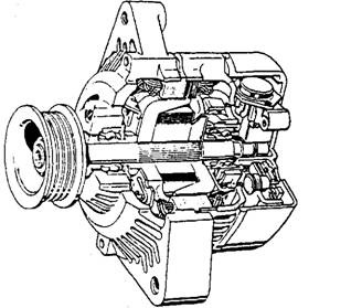
Fig. 14.5. Bosch compact alternator.
interrupt the chosen lighting circuits. An override switch is provided, for use in exceptional conditions.
A two speed drive technique using a ratio of 5 :1 for engine speeds under 1200 rpm and about 2.5 : 1 as usual at higher speeds shows some promise but at the addition of more complication to the drive system. However, the two speed drive is only at the prototype stage at present. With improvement in design alternators being produced nowadays are capable of running at higher speeds up to 20,000 rpm. If the maximum engine speed of about 6000 rpm is considered then a pulley with a ratio of about 3.3 : 1 can be used to run the alternators as fast as 2300 rpm, even with a low engine idle of 700 rpm. Figure 14.5 shows the Bosch compact alternator, capable of producing high speed and high output.
The option to increase the idle speed may not be practical due to the potential increase in
fuel consumption and emissions. This method, however, may be suitable for diesel engine powered vehicle. Some existing engine management systems are designed to receive a signal from the alternator when power demand is high. This management system then increases the engine idle speed, which prevents stalling and ensures a better alternator output. Figure 14.6 illustrates the wiring associated with this technique, which senses current in demand and controls engine idle speed.

Fig. 14.6. Alternator wiring for engine management system.
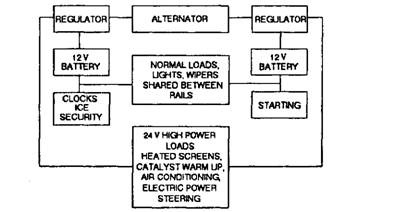
Some research is in progress on dual voltage electrical systems. It is known since long that a 24 V system is better for larger vehicle, mainly because of the use of longer lengths of wire. With double the voltage, the same power can be transmitted at half the current (power = voltage x current) resulting in a lower voltage drop. Wiring harnesses used on passenger cars are becoming increasingly heavy and unmanageable. With the higher supply voltage, the cross section of individual cables becomes half the little or no effect. Since heavy vehicle electrical have 24 V systems for a longer time, most associated components (bulls, etc.) are available. The -12, 0, +12 V technique using three bus bars or rails is discussed here. High power loads can be
connected between -12 and +12 (24 V), and loads suitable for 12 V supply can be balanced between the -12, 0 and 0, +12 V voltage supply rails. Figure 14.7 illustrates this technique.

Fig. 14.7. Dual rail power supply technique.
Figure 14.8 compares graphically some of the above mentioned techniques, applied to a vehicle when used for winter commuting. The above discussion is mostly related to design issues rather than after sales vehicle care. Nevertheless the challenge for the after sales markets is to keep abreast of the changing technology. This is often most difficult in areas associated with vehicle electrical systems.

Fig. 14.8. Graphical representation comparing various charging techniques used for winter commuting.
