14.11.
Charging Circuits Testing
Before testing of the charging circuit, the battery is to be checked first and to be assured that it is healthy and in the charged condition. If it is faulty, it has to be replaced with a good battery.
Alternator Test.
The next test is the alternator output test, illustrated in Fig. 14.35, where a test ammeter is connected either at the alternator or at the battery. The alternator field wire is removed and a jumper wire is connected between the field terminal and battery terminal on mechanically regulated internally grounded types or between the field and ground on externally grounded types. A heavy carbon pile rheostat is placed across the battery and adjusted to provide system specification voltage of approximately 14 to 15 V. The engine is started and adjusted to the specified speed of 1500 rpm. The rheostat is adjusted to maintain specification voltage and the alternator output is read.
Some manuals do not recommend the use of an ammeter, instead recommend checking the charging system while it is fully connected in its normal manner. When an ammeter is not used, alternator output is checked by measuring the system voltage while all electrical accessories are turned on and the engine is running at a specified speed.
If the alternator output is low, it is to be disassembled to check for a malfunction of each component so that it can be repaired. Failure of electrical components may be due to shorts, grounds and opens.
The short reduces circuit resistance so the conductors can carry more currents and therefore become warmer. Ground is a special form of a short, and hence has same effect as short. Shorts

Fig. 14.35. Alternator output test connection (internally grounded field alternator).
are usually checked by measuring the circuit resistance. Grounds are checked with continuity light. Opens may also be checked with continuity light. Another means of checking an open is to use a voltmeter. Any stators or field coils that are shorted, grounded, or open have to be replaced or repaired only in specialised rebuilding facilities. A disconnected diode can be checked with a 12 V DC test light. Faulty diodes are to be replaced. Occasionally the brush holders become grounded and they are checked with a 230 V test light from the brush to the alternator frame.
Voltage Drop Test.
For proper functioning of the charging system, all the conductors in the circuit must be of minimum resistance. The voltage drop through out the charging circuit is checked, while the alternator produces 20 A in the circuit, using the connections shown in Fig. 14.36, which is similar to as used for alternator output test. The voltage in an insulated charging circuit should be less than 0.7 V using an ammeter. The grounded side of the circuit should have a voltage

Fig. 14.36. Connections for measuring the charging system voltage drop with an internally grounded field alternator.
drop of less than 0.1 V. When the tests are completed successfully, the jumper wire is removed and the regulator is connected back.
Regulator Setting Check.
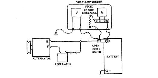
The voltage regulator limits the voltage in the charging circuit. With low setting of the regulator, the battery does not charge fully and with high setting, the service life of the ignition points, battery, electric motors, radio, lights etc. become shorten due to flow of excessive current. The battery also, as a result of excessive gassing, uses more water. The charging system voltage increases or decreases as the demand for the electrical current are less or more. A regulator under test must be placed in the system that must produce a system voltage, which is in the regulator controlling range. One way of achieving this is by installing a 1/4-Ohm series resistor in the charging circuit to add sufficient circuit resistance to increase system voltage into the regulating range. The set up is shown in Fig. 14.37.

Fig. 14.37. Measurement of charging system voltage setting.
Usually the specified range of voltage is between 14 and 15 V. Generally mechanical regulator has internal field grounds, while the solid state regulators have external field grounds. It is important to use correct applicable procedure and test specifications specified for the vehicle to obtain satisfactory regulator settings.
Mechanical voltage regulators have two sets of points, normally-closed and normally-open. Normally-closed points regulate at 0.5 V lower than the normally-open points. At set engine speeds and charging current flow, the regulated voltage can be read with a voltmeter. Mechanical regulator voltage settings are made by adjusting the spring hanger position to increase spring pressure as higher voltage is needed. Solid-state regulator are adjusted by changing the setting of a variable resistor, if they are adjustable, otherwise replaced.
