33.14.
Case/Duct System
A typical automotive heater/air-conditioner case/duct system is shown in Fig. 33.57. The purpose of the case/duct system is to house the heater core and the air-conditioner evaporator, and to direct the selected mode of air supply through these components into the passenger compartment of the car. The supply air selected may be either fresh (outside) and/or re-circulated (in-car) air, depending upon the system mode. The heated and/or cooled air is delivered to the floor outlets, dash panel outlets, and/or the defrost outlets.
Both the independent case and the split case assemblies are used to house the heater core and air-conditioner evaporator. The independent case, used on compact and small cars, may have an upstream blower, shown in Fig. 33.58A, or a downstream blower, shown in Fig. 33.58B. The independent case system is usually located under the dash-board, on the inside of the fire-well.
The split case system, which is used on larger cars, is located on both sides of the engine fire-well. An upstream integral blower (Fig. 33.59) or an independent blower (Fig. 33.60) is used in the split case system.
For the purpose of understanding, a typical hybrid case/duct system is taken up for discussion. This system is divided into air intake section, the heater core and air-conditioning evaporator section, and the air distribution section (Fig. 33.61). Air-flow is from right to left in the figure.

Fig. 33.58. Independent case system. A. Upstream blower. B. Down stream blower.

Fig. 33.59. Split case system with upstream blower.
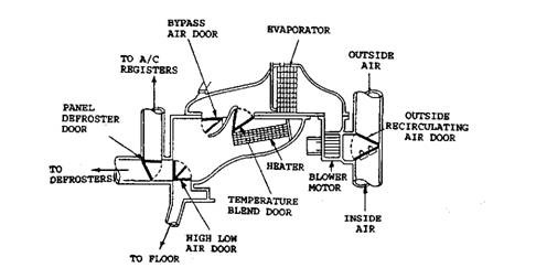
Fig. 33.60. Split case system with independent (downstream) blower.
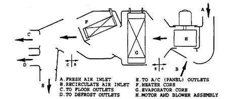
Fig. 33.61. A typical case/duct system split into the three sections.
33.14.1.
Air Intake
The air intake section or inlet section, shown in Fig. 33.62, consists of a fresh air inlet, a recirculate (inside) air inlet, a fresh-recirculate air door, a blower with motor, and an air outlet. The fresh air inlet provides the system with fresh outside air and the recirculate air inlet provides recirculated incar air supply. The position of the vacuum motor operated fresh-recirculate door depends on the system mode, as shown in Fig. 33.62 in dotted lines, for 100% fresh
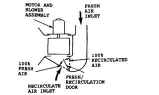
Fig. 33.62. Air inlet section.
air and 100% recirculated air conditions. Actually in all modes except maximum cooling (max A/C), the air supply is from outside. Even in max A/C mode, some systems provide for up to 20% fresh air, which increases incar pressure slightly. Normally in max A/C mode inside air is recirculated.
33.14.2.
Core Section
The core section, more appropriately called the plenum section, shown in Fig. 33.63, is the centre section of the duct system. It consists of the heater core, the air-conditioning evaporator, and a blend door. The blend door, usually Bowden cable operated, provides full-range control of airflow either through or bypassing the heater core. All the air passes through the air-conditioning evaporator. In this section full-range temperature conditions are achieved for in-car comfort.
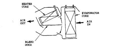
Fig. 33.63. Core section.
Heating. The heater water valve allows hot engine coolant to flow through the heater core. Cool and fresh air from outside is heated as it passes through the heater core. The air-conditioner is not operated and hence, it has no effect on the air temperature as the air first passes through the evaporator. The desired temperature is achieved by the position of the blend door, which allows a percentage of the cool outside air to bypass the heater core to temper the heated air. The heated air and cool air are then blended in the plenum to provide the desired temperature level before passing to the air distribution section.
Cooling. In the maximum cooling condition (max A/C), recirculated air passes through the air conditioner evaporator and is then directed back into the car. In other than max A/C, fresh outside air passes through the air-conditioning evaporator and is cooled before delivery into the car. The desired temperature level is achieved by the position of the blend door, which allows a percentage of cooled air to pass through the heater core for reheating. The cooled air passing through the evaporator and the reheated air passing through the heater core are blended in the plenum to provide the desired temperature level and then directed to the air distribution section.
33.14.3.
Air Distribution Section
The air distribution section (Fig. 33.64A) directs conditioned air to the floor outlets, the defrost outlets, or the dash panel outlets. Also depending upon the position of the mode doors, conditioned air may be delivered to any combination of outlets. There are two mode (blend) doors in the distribution section; the HI/LO door and the DEF/AC door. The HI/LO door, shown in Fig. 33.64B, provides zero to 100 percent full range outlet control of conditioned air to the HI (dash panel) and LO (floor) outlets. The DEF/AC door, shown in Fig. 33.64C, provides outlet control of conditioned air either to the defrost (windshield) outlets or to the dash panel outlets.
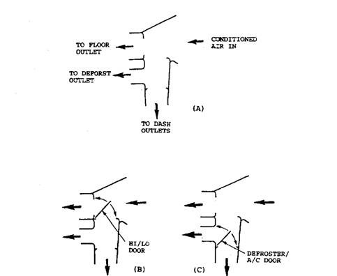
Fig. 33.64. Air distribution section.
A. Without diverter door. B. HI/LO diverter door.
C. DEF/AC diverter door.
33.14.4.
Combined Case / Duct System
The combined case / duct system provides full range control of air circulation through the heater core and air conditioner evaporator. Figure 33.65A illustrates flow of 100% recirculated air through the air conditioner evaporator and discharge through the panel eutlets. This may typically represent mode and blend door positions when maximum cooling (max A /C) is selected during high in-car temperature conditions. Figure 33.65 B illustrates 100% fresh air circulation through the heater core and discharge through the floor outlets. This may typically represent the mode and blend door positions when heating is selected during low in-car temperature conditions and no cooling is provided by the evaporator. A variation in Fig. 33.65C, shows some of the heated air is diverted to the defrost outlet. This would be the typical application to clear the windshield of fog or light icing conditions.
