10.16.
Bosch VE-type Distributor Pump
Figure 10.32 illustrates layout of a VE-type pump installed in a self-bleeding fuel system similar to that used on light vehicles. Similar to other rotary pumps, this type uses one pumping element and a number of high-pressure outlets, one for each engine cylinder.
In addition to the basic features associated with modern distributor-type rotary pumps, various add-on modules that can be incorporated to the VE-pump are:
(a) Solenoid-operated fuel cut-off to provide the driver a key to start/stop operation.
(b) Automatic cold-starting module to advance the injection.
(c) Fast-idle facility for even running during warm-up.
(d) Torque control for matching the fuel output with the fuel requirement.
The layout of the basic sub-systems of the pump is shown in simplified sectional view in Fig. 10.33. These include:
(a) Low-pressure fuel supply.
(fc) High-pressure fuel supply and distributor.
(c) Fuel shut-off solenoid.
(d) Distributor plunger drive.
(c) Automatic injection advance unit.
(/) Pressure valve.
(g) Mechanical governor.

Fig. 10.33. Bosch VE-type distributor pump.
Low Pressure Fuel Supply.
A transfer pump with four vanes is driven at half crankshaft speed by a drive shaft, and delivers fuel to the pumping chamber at a pressure set by the regulating valve. The fuel pressure rises with engine speed, and is used to operate the automatic advance unit. Also this provides an overflow through the pump body to aid cooling and to provide the self-bleeding feature. After passing through a small restriction at the top of the pump the surplus fuel returns back to the fuel tank.
High-Pressure Fuel Supply.
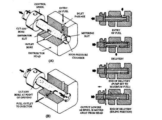
Figure 10.34 shows a simplified view of the pumping chamber with part of the distributor head cut away to view the pump plunger. The plunger is rotated in the head to provide a valve action, and is reciprocated through a constant stroke to prochjce the high pressure. A cam plate moving over a roller ring causes this axial movement. The quantity of high-pressure fuel delivered to the injector through the outlet bore is metered by the position of the control spool. This feature varies the effective pumping stroke, which increases as the spool is moved towards the distributor head.

Fig. 10.34. Principle of Bosch VE-pumping unit. A. Fuel entry to pumping chamber. B. Pump at end of delivery.
Figure 10.34A illustrates that rotation of the plunger has caused one of the metering slits to open the inlet passage and all outlet ports are closed in this position. Prior to this point, the plunger moved down the chamber for the fuel to enter and fill the high-pressure chamber. Further rotation of the plunger closes the inlet port and the single distributor slit in the plunger opens one of the outlet ports. In this position the plunger has moved up the chamber to pressurise the fuel and deliver it to the injector through the outlet bore.
Figure 10.34B illustrates the position of the plunger at the end of the injection period. The plunger has moved further considerably to uncover the Cut-off bore in the plunger, which causes the pressure to draw instantly and terminate the injection. Further movement of the plunger permits the fuel in the pumping chamber to be returned to the pump cavity. The control spool is set in this maximum fuel position corresponding to the fuel requirement for starting. A movement of the control spool to an extreme position away from the distributor head.which is the spool setting for slow running, reduces the output to a minimum.
Fuel Shut-off.
A solenoid operated valve cuts off the fuel supply to the inlet passage when the ignition key is switched off.
Distributor Plunger Drive.
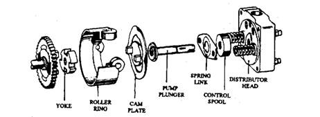
Rotation of the drive shaft, at half crankshaft speed (for a four stroke engine), is relayed through a yoke and cam plate to provide rotary motion to the pump plunger. Reciprocating motion to the plunger is provided by the rotation of a cam plate over four roller followers attached to a roller ring. In a pump for a four-cylinder engine, four lobes are formed on the cam plate and contacts between the plate and rollers are maintained by two strong plunger return springs. A yoke placed between the drive shaft and the cam plate permits the plate to move axially while maintaining a drive.

Fig10.35. Plunger drive.
Pressure Valve.
A delivery valve, of similar construction to that used on in-line pumps, is installed in the distributor head at the connection point to the high-pressure fuel lines. This valve eliminates necessity of bleeding the high-pressure fuel lines.
Automatic Injection Advance Unit.
The roller ring assembly is fixed loosely to the casing, so that it can be partially rotated through an angle of up to 12 degrees. This permits the automatic advance mechanism (Fig. 10.36) to vary the injection timing.
When the pump is operated, fuel under pressure from the transfer pump is delivered to the timing advance chamber through the pump cavity. An increase in the pump speed also increases the transfer pump pressure and flow so that the timing advance piston is moved against its spring. This causes the actuating pin to rotate the roller ring in a direction opposite to the direction of rotation of the drive shaft.
