13.6.
Battery Construction
Container.
A moulded box (Fig. 13.57), divided into a number of compartments or cells (six for a 12 volt battery or three for a 6 volt unit), is used as container. The material of the container must have high acid-proof and insulating properties and considerable mechanical strength. Nowadays polypropylene is commonly used, in place of the heavy bulky hard rubber compounds used earlier.
Ribs are moulded on the bottom of the cells so that the plate assembly rests on them and any active material falling from the plates does not bridge across the bottom of the plates. A lid
with vent plugs or multi-cell lift-up vent tops forms the top cover for the cells, and the joint between this cover and the casing is generally heat-sealed to increase the rigidity of the battery box.
Plates.
Plates (Fig. 13.57) are made of lead and are constructed in the form of a lattice grid that supports the active material and conducts the electricity to and from it. Usually the lead is alloyed with small amount of antimony or calcium, for its easy casting or cold working and for improving its mechanical and electrical properties. The windows of both the positive and the negative grids are filled with special preparation of lead oxide (PbO) paste. The plates then undergo the process known as forming where they are electrically charged, so that the paste is converted to a special spongy form of grey lead (Pb) on the negative plate and to a brown paste of lead peroxide or lead dioxide, (PbC*2) on the positive plate.
Separators.
Separators (Fig. 13.57) are placed between the plates to prevent the plates

Fig. 13.57. A single battery cell in sectional.
from touching, so that short circuiting between them due to opposite polarity is avoided. Separators in sheet form are made from non-conducting but porous material to minimize interference with the chemical action between the plates. The side of the separators facing the positive plates is normally grooved for free circulation of the electrolyte. Several materials such
as special types of wood, ebonite, glass wool, porous rubber, resin-bonded cellulose, and most commonly used sintered polyvinyl chloride (PVC) have been used for separators.
Plate Groups.
Each cell has both positive and negative groups of plates, and the two groups are interleaved with each other (Fig. 13.58A). There always exist an odd number of plates, and the extra one is the negative due to the greater chemical reaction around the positive plates.
The current carrying capacity of a battery, in other words the cells’ capability to provide a continuous supply of current, depends mainly on the total active exposed areas of the two dissimilar (positive and negative) plates. Therefore, the number of plates in each group is decided on the basis of the storage capacity of the battery to be designed.
A lead alloy strap is welded in position to the plates of the same polarity for interconnection and the strap in turn is linked to the inter-cell with a bridge connector (Fig. 13.57). Car batteries normally have either seven or nine plates per cell i.e. three positive and four negative or four positive and five negative respectively.

Fig. 13.58. Battery cell plate grouping and symbolic representation.
Cells are connected in series in which the positive pole of one cell is connected to the negative pole of the adjacent cell. For a cell with a nominal potential of 2V, three cells are connected in series to make a 6 volt battery or six cells for a 12 volt battery. External terminal posts are welded to the connected link straps of the two end cells of a battery so that one post is of positive polarity and the other negative for external connection of the battery.
Battery cells are commonly represented by two parallel lines, a long thin line for the positive plates and by a short thick line for the negative plates (Fig. 13.58B). The representation of a group of battery cells is shown in Fig. 13.58C.
Terminal Posts and Lugs.
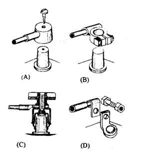
The two battery terminal posts and lugs serve as junction points for connection to the various wiring circuits. These posts must be properly sized and well supported by the battery lid to absorb the high current discharge during engagement of the starter motor, vehicle vibration, rough handling during connection or disconnection of the battery, corrosion, and the constant pull of the heavy cable.
The various methods of attachment are illustrated in Fig. 13.59. Figure 13.59B is the most suitable for heavy-duty applications, but for light duty Fig. 13.59D is commonly used. Figure 13.59C is^ very popular as it does not require any spanner or screwdriver to remove it, whereas Fig. 13.59A is practically obsolete nowadays.

Fig. 13.59. Battery terminal posts and lugs.
A. Die-cast hamlet lug.
B. Clamp lug.
C. Quick-release screw-on terminal.
D. Eyehole lug.
