33.13.
Automatic Temperature Control
The automatic temperature control refers to the maintenance of passenger compartment temperature and humidity at a preset level, regardless of the outside weather conditions. Therefore, the temperature control also holds the relative humidity in the compartment at a suitable level and prevents window fogging. If the preset temperature is 297 K (24 C), the automatic control system maintains the environment at 297 K with 45 to 55 percent humidity. In the hottest weather, the cooling system can rapidly cool the automobile interior to the predetermined temperature and cycles to maintain the temperature level. During cold weather, the system rapidly heats the passenger compartment to the temperature level and then automatically maintains it.
Many automotive electronic temperature control systems incorporate self-diagnostic test provisions where an on-board microprocessor controlled subsystem displays a code. This code indicates the cause of the malfunction. Some systems also display a code to indicate the computer which detects the malfunction. The code usually is a number, letter or alphanumeric, which varies from car to car.

Fig. 33.51. Typical thermistor.
33.13.1.
Sensors
Sensors are extremely sensitive to slight variation in temperature, though they may be different in physical appearance. The sensor is actually a resistor whose resistance value is determined by its temperature. The change in the resistance value of each sensor is inversely proportional to the change in temperature. This type of resistor is called a thermistor, shown in Fig. 33.51.

Fig. 33.52. Typical flow chart for electronic temperature control system.
33.13.2.
Electronic Temperature Control System
Many types of electronic temperature control systems are in use. The flow chart shown in Fig. 33.52 illustrates a typical system with five inputs. The following information relates to many of the components present in an electronic temperature control system.
33.13.3.
Temperature Controls Devices
Control Panel.
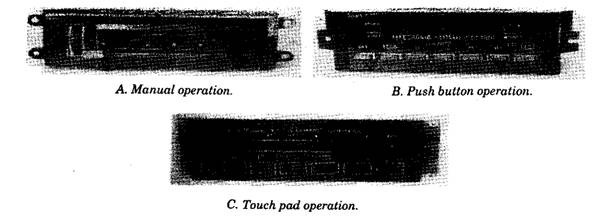
The control panel is found in the instrument panel at a convenient location giving access to both the driver and front-seat passenger, and enables the operator to provide input control to the air-conditioning and heating system. The control panel may be of manual, push button, or touch pad type (Fig. 33.53A, B and C). Provisions are made on the control panel for the selection of compartment temperature between 320 K and 330 K in one degree increments.

Fig. 33.53. Control panel.
Usually, a microprocessor is located in the controls head to provide input data to the programmer, based on operator-selected conditions. When the ignition switch is turned off, a memory circuit stores the previous settings. These conditions are restored when the ignition switch is turned on again. But if the battery is disconnected, the memory circuit becomes clear and hence requires reprogramming.
Programmer.
The programmer, installed in the control system, receives electrical signals from the sensors and the main control panel. Based on the inputs, the programmer provides output signals to turn the compressor clutch OFF/ON, CLOSE/OPEN the heater water valve, determine blower speed, and position all MEX/BLEND mode doors.
The blower and clutch controls convert low-current signals from the control panel to high-current feed to the blower motor. The speed is controlled through a resistor strip on the temperature door actuator. A power transistor circuit is included in the blower control system, which engages the compressor clutch circuit.
Power Module.
The power module controls the operation of the blower motor. The power module amplifies the blower-drive signal from the programmer. Its output signal is proportional to its input signal. This provides variable blower speed as determined by car inside conditions.
Clutch Diode.
The electromagnet clutch produces a strong magnetic field when current is applied. When power is removed the magnetic field collapses and creates high-voltage spikes. These spikes are harmful to the computer and must be prevented. A diode placed across the clutch coil provides a path to ground, holding the spikes to a safe level. This is usually taped inside the clutch coil connector, across the 12 V lead and ground lead.
High-side Temperature Switch.
The high-side temperature switch is located in the air-conditioning system liquid line between the condenser outlet and expansion valve inlet. Although it is a temperature sensing device, it provides pressure data to the processor pertaining to air conditioner system.
Low-side Temperature Switch.
The low-side temperature switch is located in the system between the expansion valve outlet and the evaporator inlet. Its purpose is to sense low-side refrigerant pressure and to provide information to the processor.
Both low-side and high-side temperatures are determined by system pressure based on the temperature/pressure relationship of R-12.
High-pressure Switch.
The high pressure switch is normally closed. It opens if air-conditioning system pressure exceeds 2930 to 2953 kPa. It re-closes when the system pressure drops below 1379 kPa. This switch provides system safety if, for any reason, pressures exceed safe limits. This switch does not provide data to the processor, and is usually in-line with the compressor clutch circuit.
Low-pressure Switch.
The low-pressure switch is located in the low side of the air-conditioning system, usually on the accumulator. This switch is normally closed. It opens when system low-side pressure drops below 14 to 55 kPa and signals the processor to stop the compressor by disengaging the compressor clutch circuit. Low-pressure conditions may result due to a loss of refrigerant or a clogged orifice tube.
Pressure Cycling Switch.
The pressure cycling switch is used in some systems to control temperature by opening and closing the electrical circuit to the compressor clutch coil. The switch usually opens at a low pressure of 172 to 179 kPa and closes at a high pressure of 317 to 311 kPa. In some systems, this switch is in-line with the compressor clutch coil and in other systems it sends data to the processor to turn the compressor on and/or off.
Sun-load Sensor.
The sun-load sensor is a photovoltaic diode that sends an appropriate signal to the processor to support in regulating the compartment temperature. The sensor is normally located at top of the dashboard, adjacent to one of the radio speaker grilles.
Outside Temperature Sensor.
The outside temperature sensor is usually placed just behind the radiator grille and in front of the condenser. It senses outside temperature and provides temperature information to the processor. This sensor circuit includes several programmed memory features, which prevents false ambient temperature data input during periods of low-speed driving or while stopping for a traffic signal.
In-car Temperature Sensor.
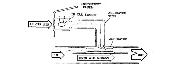
The in-car temperature sensor, also called an in-vehicle sensor is located in a tubular device, called an aspirator. A small amount of in-car air is drawn through the aspirator across the in-car sensor to provide average in-car temperature data to the processor.
Aspirator.
The aspirator is a small duct system (Fig. 33.54) through, which a small amount of incar air passes. The main air stream creates a low pressure (suction) at the inlet end of the aspirator due to which in-car air is drawn into the sensor plenum. The in-car sensor, located in the plenum, continuously monitors the average inside air temperature.

Fig. 33.54. A typical aspirator.
Coolant Temperature Sensor.
The coolant temperature sensor is a thermistor, which provides engine coolant temperature information to the processor. This sensor also provides input information to other on-board computers regarding fuel enrichment, ignition timing, exhaust gas recirculation, canister purge control, idle speed control, and closed loop fuel control.
A defective coolant temperature sensor causes poor engine performance, which is normally observed before poor air-conditioning performance is experienced.
Vehicle Speed Sensor.
The vehicle speed sensor is a pulse generator located at the transmission output shaft. It provides actual vehicle speed data to the processor as well as other subsystems, such as the electronic control module.
Throttle Position Sensor.
The throttle position sensor is actually a potentiometer with a voltage input from the processor. The processor, in turn, determines throttle position based on the return voltage signal. At the wide open throttle position the compressor clutch is disengaged to provide maximum power for acceleration. This device is often called the wide open throttle sensor and is normally found on diesel engine powered vehicles.
Heater Turn-on Switch.
The heater turn on switch is usually a bimetal snap-action switch installed in the coolant stream of the engine. The switch prevents blower operation when engine coolant temperature is below 322 to 323 K, if heating system is selected. On the other hand if cooling system is selected, the programmer overrides this switch to operate the blower immediately regardless of engine coolant temperature.
Brake Booster Vacuum Switch.
The brake booster vacuum switch is used on some cars to disengage the air-conditioning compressor when braking requires maximum effort. This switch is usually in-line with the compressor clutch electrical circuit and does not provide data to the processor.
Power Steering Cut-off Switch.
The power steering cut-off switch is used on some cars to disengage the air conditioning compressor when power steering requires maximum effort. This switch is normally in-line with the compressor control relay and may not provide data to the programmer. In addition this may be in the electronic control module to provide feedback data to the compressor.
Mode Actuators.
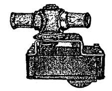
Both vacuum operated and electric operated mode actuators are used to position the mode doors. Vacuum operated actuators, often called ‘pots’ or ‘motors’ are covered under section 33.10.2. The electric mode actuator (Fig. 33.55) have both drive and feedback circuitry. This allows any positioning through 360 degrees of travel, but movement is only in one direction. The feedback circuit provides constant data to the control panel relative to the position in which it is stopped. If correct feedback signal is not received by the control panel within twenty seconds, power to the actuator turns off and an LED flashes on the control panel to warn the operator.

Fig. 33.55. Typical electric mode actuator.

Fig. 33.56. A typical electric operated water valve actuator.
Water Valve Actuator.
Both vacuum and electric operated water valve actuators are in use. The vacuum operated actuators are discussed under section 33.10.1. The electric water valve actuator (Fig. 33.56) operates in a manner similar to the mode actuator, except that it can travel in both the direction and has a travel only through 90 degrees. The water valve provides water to the heater core, which is located in the air conditioning/heating duct system. The actuator turns the water valve on and off.

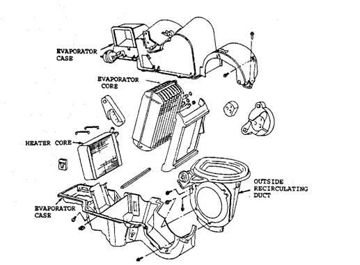
Fig. 33.57. Exploded view of a typical duct system.
